
High-density low-loss optical fiber connector and connection method

A fiber optic connector and low-loss technology, applied in light guides, optics, instruments, etc., can solve the problems of insufficient firmness of the fixing device, loose fiber interface, high fiber loss, etc., achieve good elastic support effect, prevent loose connection, and good sealing effect Effect

Active Publication Date: 2020-12-11
ANNING BUREAU OF ULTRA HIGH VOLTAGE TRANSMISSION
View PDF5 Cites 0 Cited by
  • Summary
  • Abstract
  • Description
  • Claims
  • Application Information

AI Technical Summary

Problems solved by technology

The traditional fiber optic connector is easy to loose after connection, and the fixing device is not strong enough to withstand the test of some harsh environments, resulting in loose fiber interface, resulting in high fiber loss; and it is inconvenient to adjust the docking position when the fiber is connected Minimizes the loss caused by the fiber optic connection

Method used


Image

  • High-density low-loss optical fiber connector and connection method
  • High-density low-loss optical fiber connector and connection method
  • High-density low-loss optical fiber connector and connection method

Examples


Embodiment 1

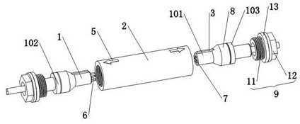
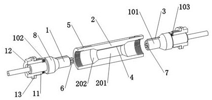
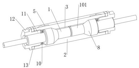
[0033] The present invention provides such Figure 1-6 A high-density and low-loss optical fiber connector is shown, including a first connector 1, a second connector 101 and a sleeve 2, one end of the first connector 1 is provided with a pin 6, and one end of the second connector 101 is provided with a pinhole 7, and the pin 6 is matched and inserted in the pin hole 7 for data connection and transmission, combined with figure 2 and image 3 As shown, the sleeve 2 is sleeved at the junction of the first joint 1 and the second joint 101, and the inside of the sleeve 2 is provided with a first positioning inner cavity 201, and the inner wall of the first positioning inner cavity 201 is aligned with the first joint 1 1. The outer wall of the second joint 101 is matched and in contact, so as to prevent offset between the first joint 1 and the second joint 101 .

[0034] to combine figure 1 , figure 2 and image 3 As shown, the outer walls of the first joint 1 and the second...

Embodiment 2

[0039] The inventors of the present case discovered during the implementation of the above-mentioned embodiment 1 that when using the connector, respectively insert the first joint 1 and the second joint 101 into the sleeve 2 according to the indication of the indicator arrow 5, and the guide rib 3 and the Insert the pin 6 into the pinhole 7 under the positioning of the guide groove 4, and then use the torque wrench to rotate the hexagonal stud ends 12 on both sides to squeeze the first elastic washer 102 and the second elastic washer 103, and the first elastic washer 102 squeezes Pressing the first joint 1 , the second elastic washer 103 presses the second joint 101 , further inserting the pin 6 into the pin hole 7 , and preventing the pin 6 from coming out of the pin hole 7 . In the above process, in order to ensure the normal conduction of the optical fibers on both sides and determine the optical signal transmission loss of each connecting part, after the pin 6 is inserted ...


PUM


Abstract

The invention discloses a high-density low-loss optical fiber connector and a connection method, and belongs to the field of optical fiber connectors. The high-density low-loss optical fiber connectorcomprises a first joint, a second joint and a sleeve; the sleeve sleeves the connection position of the first joint and the second joint; two end openings of the sleeve are connected with pressing covers through threads; a first elastic washer and a second elastic washer are arranged between the inner end of each pressing cover and the outer end of a corresponding anti-loosening body. According to the high-density low-loss optical fiber connector and the connection method of the invention, the pressing covers are used for jacking the conical anti-loosening bodies in the middles of the first joint and the middle of the second joint, it is guaranteed that the anti-loosening bodies are tightly attached to the inner wall of a second positioning inner cavity, and the first joint and the secondjoint are prevented from deviating and loosening in the radial direction in the sleeve; the first elastic washer and the second elastic washer have a good elastic supporting effect, so that connection looseness between the first joint and the second joint is prevented, a good sealing effect is achieved; the connection positions of optical fibers on two sides can be adjusted through the second elastic washer, and losses are reduced to the minimum.

Description

technical field [0001] The invention relates to the field of optical fiber connectors, in particular to a high-density and low-loss optical fiber connector and a connection method. Background technique [0002] The main function of the fiber optic connector is to quickly connect two optical fibers so that the optical signal can be continuous to form an optical path. The insertion loss is caused by the lateral deviation between the two connected optical fibers, the longitudinal gap in the optical fiber connector and the quality of the end face. Usually the outer diameter of the optical fiber is only 125um, and the light-passing part is smaller. The single-mode optical fiber is only about 9um, and the multimode optical fiber is only about 9um. Optical fibers are available in various forms such as 50 / 125um, 62.5 / 125um, 105 / 125um, and 200 / 220um, so the connection between optical fibers requires precise alignment. The traditional fiber optic connector is easy to loose after conn...

Claims


Application Information

Patent Timeline
IPC IPC(8): G02B6/38
CPCG02B6/389G02B6/3869
Inventor 阮峻孙豪朱志俊毛文俊李俊宇邱桂尧杜浩滔
Owner ANNING BUREAU OF ULTRA HIGH VOLTAGE TRANSMISSION
Learn More