A transformer coil winding device

A transformer coil and winding device technology, which is applied in the direction of inductance/transformer/magnet manufacturing, coil manufacturing, electrical components, etc., can solve the problems of wasting manpower, transformer scrapping, and transformer performance degradation, so as to achieve good practicability and prevent loose parts Effect

Active Publication Date: 2022-07-01
溆浦萬聚电子科技有限公司
View PDF0 Cites 0 Cited by
  • Summary
  • Abstract
  • Description
  • Claims
  • Application Information

AI Technical Summary

Problems solved by technology

[0003] At present, the traditional winding work usually adopts manual winding, but the efficiency of manual winding is extremely low, wastes manpower, and may cause the transformer to be scrapped due to human error in operation. In order to solve the manual problem, machine winding appears on the market. However, when the machine is winding, the winding speed of the machine is uncontrollable, and the number of winding turns cannot be well controlled, resulting in the index of the winding coil not up to the standard, which greatly reduces the performance of the transformer produced in the later stage, and the existing The winding device cannot play the role of facilitating loading and unloading

Method used


Image

  • A transformer coil winding device
  • A transformer coil winding device
  • A transformer coil winding device

Examples


Embodiment 1

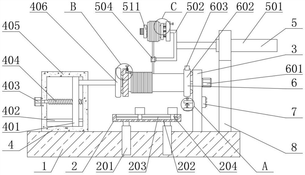
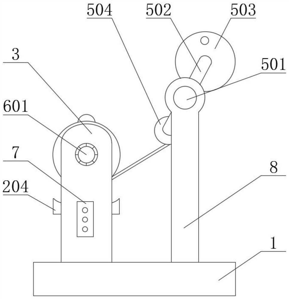
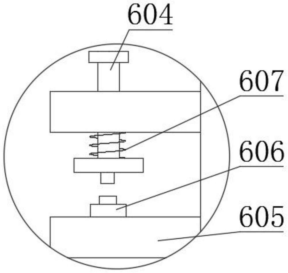
[0029] see Figure 1-7 , the present invention provides a kind of technical scheme:

[0030] A transformer coil winding device, comprising a base 1, a side plate 3 fixedly connected to the top of the base 1, and a support ring 8 fixedly connected to the top of the base 1, characterized in that the support ring 8 is arranged on the right rear side of the side plate 3, The right end of the plate 3 is fixedly connected with the controller 7, and the side plate 3 is provided with a rotating circle marking mechanism 6, which can realize accurate counting of the number of turns, and the rotating circle marking mechanism 6 includes a fixed plate 605 and a second motor. 601, the inner side of the fixed plate 605 on the upper side is slidably connected with a push rod 604, the outer side of the push rod 604 is provided with a second spring 607, and the two ends of the second spring 607 are respectively connected with the bottom end and the bottom end of the fixed plate 605 on the upper...

Embodiment 2

[0034] Workflow: In Example 2, the same parts as in Example 1 will not be repeated, the difference is that when feeding, the lifting screw 901 is rotated, and the lifting screw 901 can move upward. When the lifting screw 901 moves upward, The lifting screw 901 will drive the telescopic plate 902 to move upward, one end of the coil 506 will be sent away, the first electric telescopic rod 201 will be stretched, the support plate 204 will be close to the lower side of the iron rod, and the first motor 403 will drive the first screw 404 to rotate, The first screw 404 drives the outer slide plate 401 to move to the left, wherein the set second limit rod 402 plays a limiting role, which can increase the stability of the slide plate 401 when it moves. When the slide plate 401 moves to the left, The sliding plate 401 drives the top plate 406 to move to the left, and the top plate 406 drives the left splint 407 to move to the left. At this time, the iron rod will move downward under the...


PUM


Abstract

The invention relates to the technical field of transformer production, in particular to a transformer coil winding device, comprising a base, a side plate fixedly connected to the top of the base, and a support ring fixedly connected to the top of the base. The right end of the side plate is fixedly connected with the controller, and the side plate is provided with a rotating ring-marking mechanism. The component can realize the accurate calculation of the number of winding coils, and has good practicability. The second motor drives the right splint to rotate. During the rotation of the right splint, every time the right splint rotates one circle, the bump on the right splint will press The ejector rod moves downward, and the downward movement of the ejector rod will overcome the elastic force of the second spring and press the pressing counter to count. And reciprocate in this way to realize the counting of the number of turns of the coil.

Description

technical field [0001] The invention relates to the technical field of transformer production, in particular to a transformer coil winding device. Background technique [0002] Transformers are widely used in the power industry. The transformer is a conversion device that uses the principle of electromagnetic induction to change the AC voltage. It has the functions of voltage conversion, current conversion, impedance conversion, etc. In the process of making a transformer, the coil inside the transformer needs to be wound. , in the winding process, there are strict regulations on how many turns to be wound. [0003] At present, the traditional winding work usually adopts manual winding, but the efficiency of manual winding is very low, wastes manpower, and the transformer may be scrapped due to operator errors. However, when the machine is wound, the winding speed of the machine is uncontrollable, and the number of winding turns cannot be well controlled, resulting in the w...

Claims


Application Information

Patent Timeline
Patent Type & Authority Patents(China)
IPC IPC(8): H01F41/06H01F41/096H01F41/094H01F41/082
CPCH01F41/06H01F41/096H01F41/094H01F41/082
Inventor 向祚水
Owner 溆浦萬聚电子科技有限公司
Why Eureka
Try Eureka