Metallized polypropylene film capacitor

A polypropylene film and capacitor technology, which is applied in the field of capacitors, can solve problems such as loose capacitor parts, vibration of power equipment, and damaged capacitors

Inactive Publication Date: 2020-12-11
张丽华
View PDF4 Cites 0 Cited by
  • Summary
  • Abstract
  • Description
  • Claims
  • Application Information

AI Technical Summary

Problems solved by technology

[0003] In the existing society, when metallized polypropylene film capacitors are installed on large-scale power equipment, the space for metallized polypropylene film capacitors that can be installed is limited, and it is impossible to install shock absorbers on the capacitor's installation site, while The larger the power equipment, the greater the impact of its own gravity and structure. The power equipment will vibrate when it is working, and the capacitor will run in a long-term vibration environment, which will cause problems such as loosening of the internal parts of the capacitor and damage the capacitor.

Method used


Image

  • Metallized polypropylene film capacitor
  • Metallized polypropylene film capacitor
  • Metallized polypropylene film capacitor

Examples


Embodiment 1

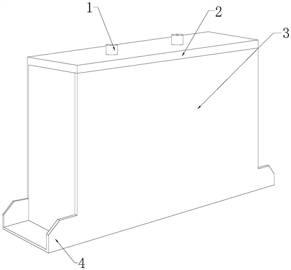
[0029] see Figure 1-Figure 5 , a metallized polypropylene film capacitor, its structure includes a terminal 1, a closing cover 2, an equipment box 3, and a mounting bracket 4, the terminal 1 is installed on the closing cover 2, and the closing cover 2 is installed on the equipment box 3, the mounting bracket 4 and the equipment box 3 are an integrated structure;

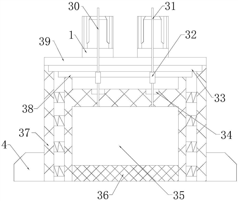
[0030] The equipment box 3 is provided with a positive pole 30, a negative pole 31, a fuse 32, an explosion-proof cover 33, a connection hole 34, a capacitor core 35, a bottom shock absorber 36, a side anti-vibration body 37, a heat dissipation cover 38, and an end cover 39. The positive pole 30 is installed on the end cover 39, the side of the end cover 39 is provided with the negative pole 31, the explosion-proof cover 33 is provided under the end cover 39, and the heat dissipation cover 38 is installed on the explosion-proof Below the cover plate 33, the fuse 32 is fixedly installed with the positive electrode r...

Embodiment 2

[0037] see Figure 1-Figure 7 , a metallized polypropylene film capacitor, its structure includes a terminal 1, a closing cover 2, an equipment box 3, and a mounting bracket 4, the terminal 1 is installed on the closing cover 2, and the closing cover 2 is installed on the equipment box 3, the mounting bracket 4 and the equipment box 3 are an integrated structure;

[0038] The equipment box 3 is provided with a positive pole 30, a negative pole 31, a fuse 32, an explosion-proof cover 33, a connection hole 34, a capacitor core 35, a bottom shock absorber 36, a side anti-vibration body 37, a heat dissipation cover 38, and an end cover 39. The positive pole 30 is installed on the end cover 39, the side of the end cover 39 is provided with the negative pole 31, the explosion-proof cover 33 is provided under the end cover 39, and the heat dissipation cover 38 is installed on the explosion-proof Below the cover plate 33, the fuse 32 is fixedly installed with the positive electrode r...


PUM


Abstract

The invention discloses a metallized polypropylene film capacitor. Themetallized polypropylene film capacitor structurally comprises a wiring terminal, a closing cover, an equipment box and a mountingbracket. A damping vibration isolation layer is arranged on the surface of the vibration isolation block of the metallized polypropylene film capacitor, and the vibration of equipment is reduced through a vibration isolation method; the long-strip shaft of an overturning block separates the wall of the equipment from the vibration isolation block by a certain distance to prevent the acting forceof vibration from being directly transmitted to the vibration isolation block, and an arc-shaped spring shaft is connected to the included angle of the long-strip shaft of the overturning block, so that when the equipment vibrates, one part of the acting force of vibration is transmitted to the long-strip shaft of the overturning block; and the wall body connected between the pieces of equipment can press the overturning block backwards, the spring shaft is arranged on the included angle of the long-strip shaft, a spring has the springback characteristic and forms counter-acting force with theoverturning extrusion force of the long-strip shaft, energy generated by vibration can be consumed in the mutual abutting and buckling movement of component force of the equipment, and the vibrationreduction effect is achieved.

Description

technical field [0001] The invention relates to the field of capacitors, in particular to a metallized polypropylene film capacitor. Background technique [0002] Metallized polypropylene film has become one of the main materials for capacitors. Metallized polypropylene film has the characteristics of low loss, good stability, high volume resistivity, and small thermal shrinkage. Therefore, metallized polypropylene film is used in electric power Widely used in equipment capacitors; [0003] In the existing society, when metallized polypropylene film capacitors are installed on large-scale power equipment, the space for metallized polypropylene film capacitors that can be installed is limited, and it is impossible to install shock absorbers on the capacitor's installation site, while The larger the power equipment, the greater the impact of its own gravity and structure. The power equipment will vibrate when it is working, and the capacitor will run in a long-term vibration ...

Claims


Application Information

Patent Timeline
Patent Type & Authority Applications(China)
IPC IPC(8): H01G4/33F16F15/02F16F15/067H01G2/16H01G4/224
CPCF16F15/02F16F15/067H01G2/16H01G4/224H01G4/33
Inventor 张丽华
Owner 张丽华
Why Eureka
Try Eureka