Supercharge Your Innovation With Domain-Expert AI Agents!

Unmanned aerial vehicle navigation decoy signal generation antenna

A signal generation and unmanned aerial vehicle technology, applied in the directions of antennas, antenna parts, antenna supports/installation devices, etc., can solve problems such as difficult disassembly, and achieve the effects of convenient disassembly, realization of protection, and simple design structure.

Active Publication Date: 2020-12-11
成都安则科技有限公司
View PDF7 Cites 0 Cited by
  • Summary
  • Abstract
  • Description
  • Claims
  • Application Information

AI Technical Summary

Problems solved by technology

[0004] The purpose of the present invention is to provide a UAV navigation decoy signal generating antenna, to solve the problem of the UAV navigation decoy signal generation antenna in the prior art proposed in the above background technology. When installing, it is fixed by bolts. Good, but the problem of not being easy to disassemble

Method used


Image

  • Unmanned aerial vehicle navigation decoy signal generation antenna
  • Unmanned aerial vehicle navigation decoy signal generation antenna
  • Unmanned aerial vehicle navigation decoy signal generation antenna

Examples


Embodiment 1

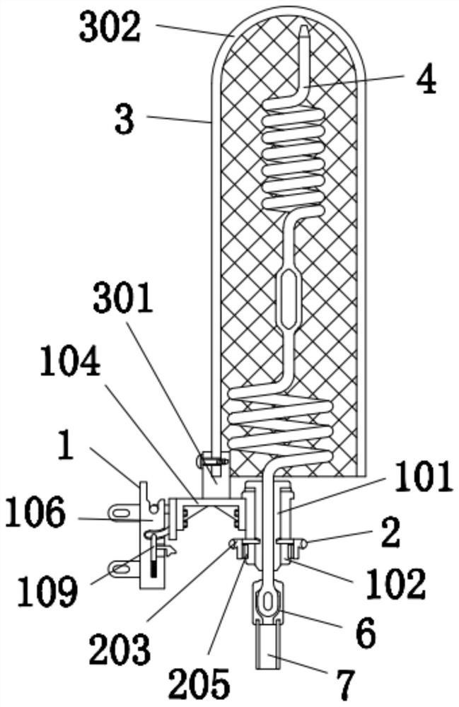
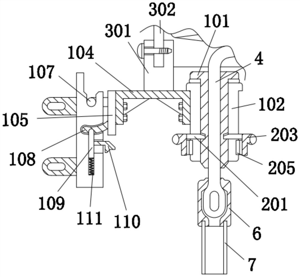
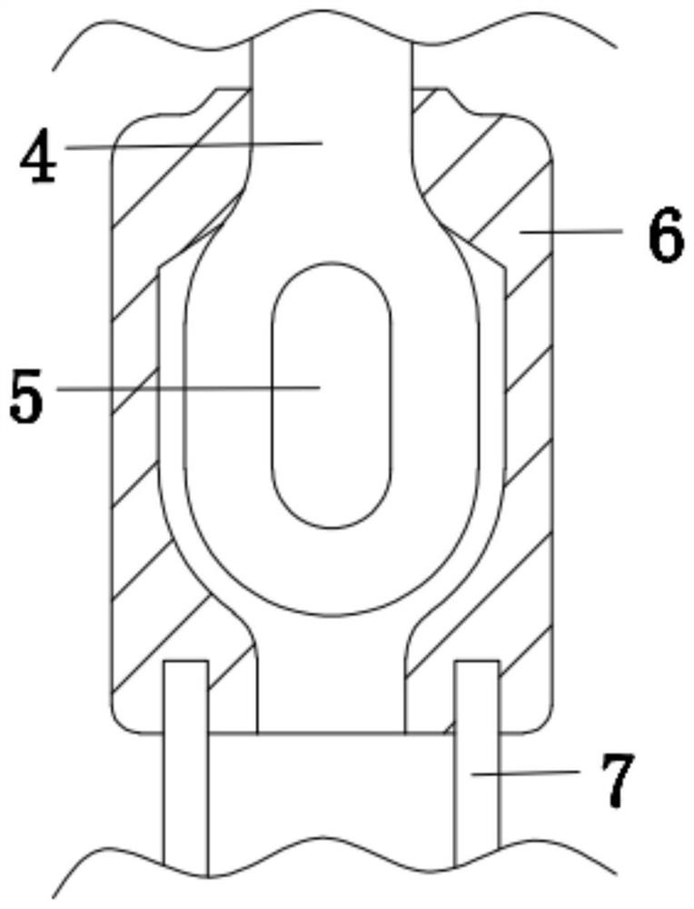
[0035] A UAV navigation decoy signal generation antenna, including an antenna 4, the antenna 4 is an UAV navigation decoy signal generation antenna, the specific model is not limited, and the left side of the outer wall of the antenna 4 is provided with an installation device 1, and the installation device 1 includes Thin tube 101, thick tube 102, rubber ring 103, base 104, riser 105, base plate 106, hook 107, arc bar 108, latch 109, handle 110, spring 111 and support 112, the inner wall of thin tube 101 and antenna The outer walls of 4 are fixedly connected together, and the thin tube 101 and the thick tube 102 cooperate to limit the antenna 4. The outer wall of the thin tube 101 and the inner wall of the thick tube 102 have a clearance fit, and the outer wall of the thin tube 101 has an interference fit. There is a rubber ring 103, the rubber ring 103 ensures the tightness and friction between the thin tube 101 and the thick tube 102, the bottom of the inner wall of the rubbe...

Embodiment 2

[0037] As an option, see figure 1 , 2And 5, the UAV navigation decoy signal generation antenna, the outer wall of the thin tube 101 is provided with a fixing device 2 on the left and right sides, and the fixing device 2 includes a clamping rod 201, a clamping groove 202, a handle 203, a first magnetic plate 204 and a second magnetic plate 204. The magnetic plate 205, the clamping rod 201 is clamped together with the outer wall of the thin tube 101 through the clamping groove 202, the outer wall of the clamping rod 201 runs through the outer wall of the thick tube 102, and the clamping rod 201 plays a role of fixing the thin tube 101 and the thick tube 102 , and the outer wall of the clamping rod 201 is in clearance fit with the thick tube 102, the right end of the clamping rod 201 away from the thick tube 102 is fixedly connected with a handle 203, and the side of the handle 203 close to the thick tube 102 is fixedly connected with a first magnetic plate 204, the first magneti...

Embodiment 3

[0040] As an option, see figure 1 and 4 , UAV navigation decoy signal generation antenna, the top of the base 104 is provided with a protective device 3, the protective device 3 includes a base 301 and a mesh cover 302, the bottom of the base 301 is fixed with the top of the base 104, the top of the base 301 A net cover 302 is provided, and the net cover 302 is made of plastic, which protects the antenna 4 and prevents birds from falling on it and building nests, etc. The net cover 302 is fixed with the base 301 through screws, and the net cover 302 sets Connected above the outer wall of the antenna 4.

[0041] The solution in this embodiment can be selectively used in combination with the solutions in other embodiments.


PUM


Abstract

The invention discloses an unmanned aerial vehicle navigation decoy signal generating antenna which comprises an antenna body, and a mounting device is arranged on the left side below the outer wall of the antenna body. The unmanned aerial vehicle navigation decoy signal generation antenna is simple in design structure, convenient for operators to disassemble and assemble, very convenient to operate and capable of reducing the disassembly time, bringing convenience to maintenance personnel and avoiding the waste of time, and the substrate does not need to be taken down by the operators, so that the operation is very convenient, and the maintenance efficiency is improved through the cooperation of the thin tube, the thick tube, the support rod, the handle, the first magnetic plate and the second magnetic plate. Through cooperation of the heat shrink tube and the rubber sleeve, sealing of the connection part of the external wiring and the antenna can be ensured, the connection part of the antenna and the external wiring is prevented from being corroded, normal use of the antenna is ensured, through cooperation of the mesh enclosure and the base, protection of the antenna is realized,and the service life of the antenna is prolonged. External birds are prevented from easily falling above the antenna to defecate and nest, and the service life of the antenna is further ensured.

Description

technical field [0001] The invention relates to the technical field of drones, in particular to an antenna for generating navigation decoy signals for drones. Background technique [0002] The UAV navigation deception simulates the satellite signal emitted by the navigation satellite, and transmits its signal in a directional manner, so that the aircraft receives the decoy signal. The default is the normal navigation signal in the sky. When the position is offset in the analog signal, the aircraft will Moving in the opposite direction is the basic principle of navigation deception, where the signal transmitter is an antenna. [0003] The UAV navigation decoy signal generating antenna in the prior art is fixed by bolts during installation, and the fixing effect is good, but it is not easy to disassemble, especially the antenna in the high altitude, which is easy to be damaged. It is inconvenient for the operators, the connection between the antenna and the external wiring is...

Claims


Application Information

Patent Timeline
IPC IPC(8): H01Q1/12H01Q1/00H01Q1/42H01Q3/02
CPCH01Q1/02H01Q1/12H01Q1/1264H01Q1/42H01Q3/02
Inventor 吴庐山戎宜生项智锋凌善锋张勇
Owner 成都安则科技有限公司
Features
  • R&D
  • Intellectual Property
  • Life Sciences
  • Materials
  • Tech Scout
  • Unparalleled Data Quality
  • Higher Quality Content
  • 60% Fewer Hallucinations
Learn More