
Lead partition plate

A technology of partitions and wires, applied in the field of power grid wire protection accessories, can solve the problems of high construction cost, difficult work, complex structure of wire rodent-proof partitions, etc., and achieve the effect of simple structure and live working

Inactive Publication Date: 2020-12-11
GUANGDONG POWER GRID CO LTD +1
View PDF8 Cites 2 Cited by
  • Summary
  • Abstract
  • Description
  • Claims
  • Application Information

AI Technical Summary

Problems solved by technology

[0002] In the overhead lines of the distribution network, mice and other small animals often climb and shuttle along the overhead wires between the outdoor transformer and the line to the street yard, gnawing on the cables, destroying the insulation performance of the wires, and laying hidden dangers for the operation of the lines, which can easily cause equipment interphase And single-phase grounding short-circuit accidents, causing line tripping and power outages, endangering the reliability of power supply, and bringing economic losses to social production and life
The structure of the traditional rodent-proof partition is complicated, and multiple people are required to cooperate with the installation of climbing equipment during installation, and the maintenance work must be carried out without power, which cannot meet the requirements of live work. The construction cost is high, the work is difficult, and it cannot meet the requirements of power grid construction in the new era.

Method used


Image

  • Lead partition plate
  • Lead partition plate
  • Lead partition plate

Examples


Embodiment Construction

[0028] In order to make the technical problems solved by the present invention, the technical solutions adopted and the technical effects achieved clearer, the technical solutions of the embodiments of the present invention will be further described in detail below in conjunction with the accompanying drawings. Obviously, the described embodiments are only the technical solutions of the present invention. Some, but not all, embodiments. Based on the embodiments of the present invention, all other embodiments obtained by those skilled in the art without creative efforts fall within the protection scope of the present invention.

[0029] In the description of the present invention, unless otherwise clearly specified and limited, the terms "connected", "connected" and "fixed" should be understood in a broad sense, for example, it can be a fixed connection, a detachable connection, or an integrated ; It can be a mechanical connection or an electrical connection; it can be a direct...


PUM


Abstract

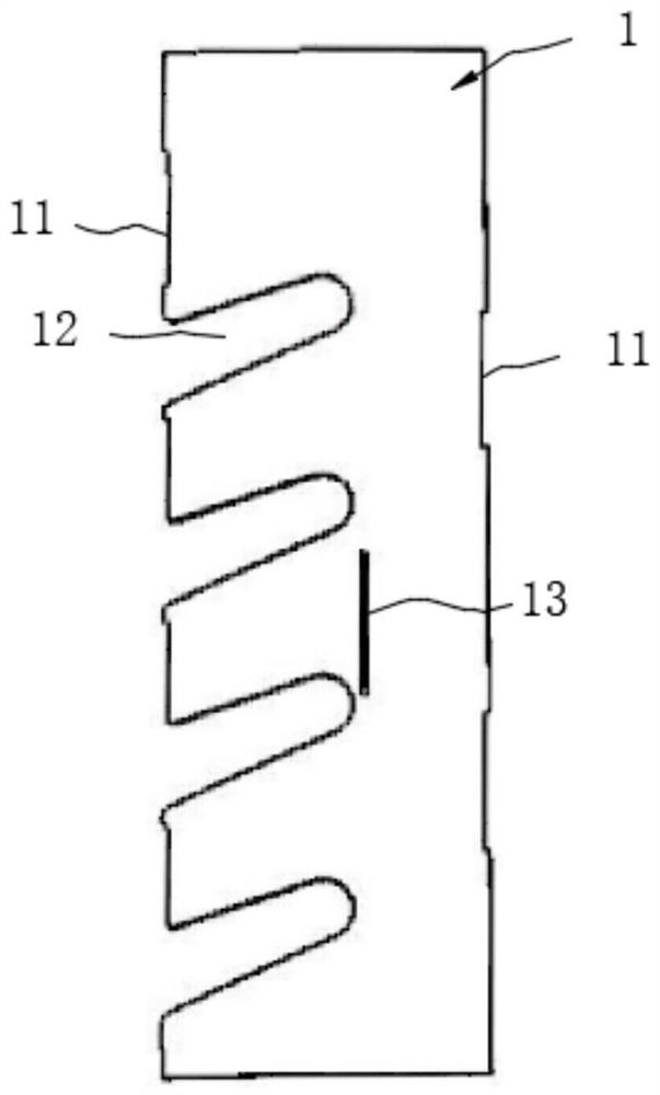
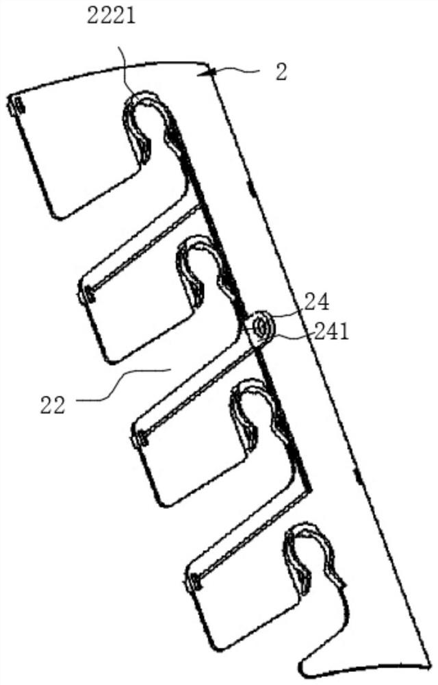
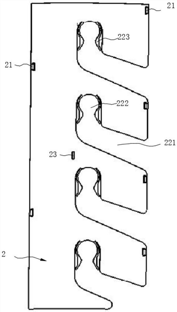
The invention discloses a lead partition plate. The lead partition plate comprises a first partition plate and a second partition plate, a first groove is formed in one side edge of the first partition plate, the first groove penetrates through the first partition plate in the thickness direction of the first partition plate, a second groove is formed in one side edge of the second partition plate, and the second groove penetrates through the second partition plate in the thickness direction of the second partition plate. The first partition plate is provided with a first binding face, the second partition plate is provided with a second binding face, the first partition plate and the second partition plate are connected through a first buckling mechanism, after the first partition plate and the second partition plate are assembled in place, the first binding face is attached to the second binding face, and the first groove and the second groove are partially right opposite to jointlyform a through hole for a wire to penetrate through. The rest part of the first groove is shielded by the second partition plate, and the rest part of the second groove is shielded by the first partition plate. The first partition plate and the second partition plate are simple in structure and convenient to assemble, through holes only allowing the wires to penetrate through are formed after assembly is completed, and climbing paths of small animals such as mice on the wires can be blocked.

Description

technical field [0001] The invention relates to the field of electric wire protection accessories, in particular to a wire separator. Background technique [0002] In the overhead lines of the distribution network, mice and other small animals often climb and shuttle along the overhead wires between the outdoor transformer and the line to the street yard, gnawing on the cables, destroying the insulation performance of the wires, and laying hidden dangers for the operation of the lines, which can easily cause equipment interphase And single-phase grounding short-circuit accidents, causing line tripping and power outages, endangering the reliability of power supply, and bringing economic losses to social production and life. The structure of the traditional rodent-proof partition for wires is complicated, and multiple people are required to cooperate with the installation of climbing equipment during installation, and the maintenance work must be carried out without power, whi...

Claims


Application Information

Patent Timeline
Patent Type & Authority Applications(China)
IPC IPC(8): H02G7/12
CPCH02G7/12
Inventor 何志强詹前东罗小超陈略思文向阳李世超黄伟欣罗庆良刘世明黄业清黄炳创
Owner GUANGDONG POWER GRID CO LTD
Learn More