
An unlocking force and stroke adjustment mechanism

A technology of stroke adjustment and locking mechanism, applied in transportation and packaging, special positions of vehicles, vehicle components, etc., can solve problems such as the inability to realize the adjustment of slide rails alone, the great influence of force and displacement space, and the limited range of adjustment. , to achieve the effect of small unlocking force, reduced part loss and large adjustment range

Active Publication Date: 2022-01-21
KEIPER (CHANGSHU) SEATING MECHANISMS CO LTD
View PDF8 Cites 0 Cited by
  • Summary
  • Abstract
  • Description
  • Claims
  • Application Information

AI Technical Summary

Problems solved by technology

[0003] The above two methods of seat comfort adjustment are not suitable for the adjustment method of the motor-driven unlocking slide rail assembly, and the adjustment of force and displacement is greatly affected by the space and the adjustment range is limited; in addition, the above seat comfort adjustment Both of the two methods need to be integrated with the seat frame, and the adjustment of the slide rail cannot be realized independently

Method used


Image

  • An unlocking force and stroke adjustment mechanism
  • An unlocking force and stroke adjustment mechanism
  • An unlocking force and stroke adjustment mechanism

Examples


Embodiment Construction

[0030] The present invention will be further described below in conjunction with the accompanying drawings and specific embodiments.

[0031] see Figure 5 , the unlocking force and stroke adjustment mechanism 100 shown in the figure includes a fixed bracket 110 , and the fixed bracket 110 is installed on the upper slide rail 310 of the slide rail assembly 300 using fasteners such as a pair of bolts 200 .

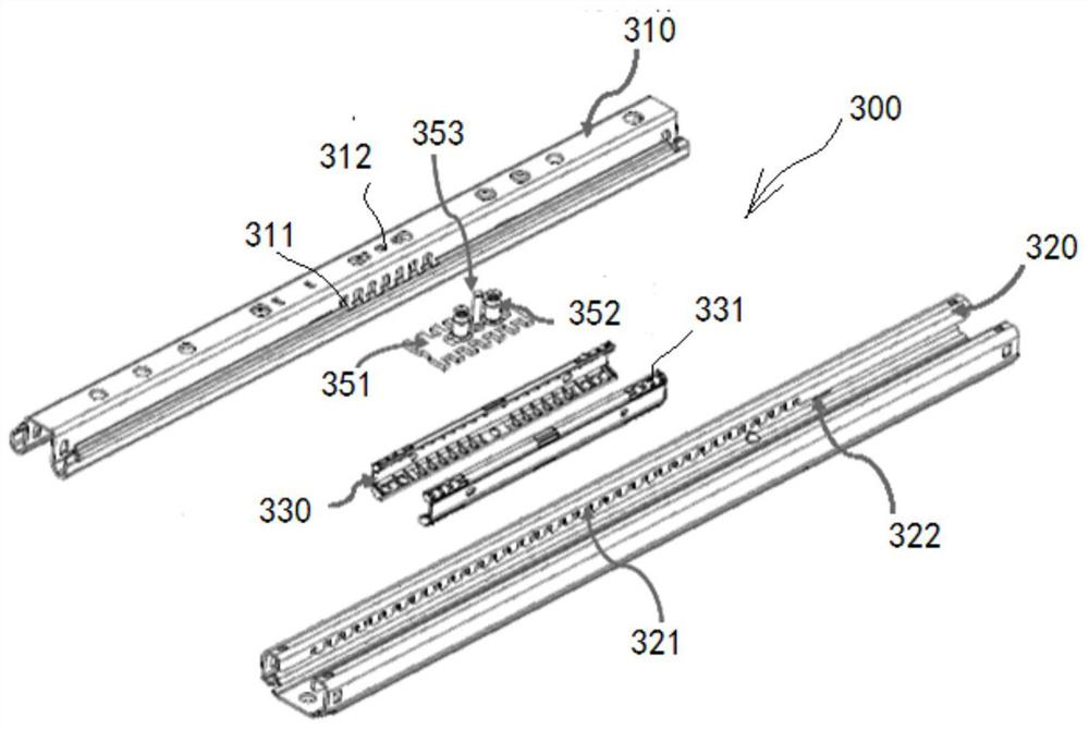
[0032] see in conjunction image 3 with Figure 4 The slide rail assembly 300 includes an upper slide rail 310, a lower slide rail 320, a pair of ball cages 330, a number of balls 331, a tooth plate 351 constituting the slide rail locking mechanism, a pair of locking springs 352 and an unlocking pin 353. The sliding rail 310 and the lower rail 320 are slidably arranged together through a pair of ball cages 330 and a plurality of balls 331 , and the pair of ball cages 330 hold the balls 331 .

[0033] The locking teeth on the tooth plate 351 pass through the upper rail to...


PUM


Abstract

The invention provides an unlocking force and stroke adjustment mechanism, which is manufactured independently of the slide rail assembly, and is installed in the upper slide rail of the slide rail assembly using fasteners. The mechanism includes a fixed bracket connected to the upper slide rail in the slide rail assembly and an unlocking U-shaped bracket assembly installed in the above-mentioned fixing bracket, an unlocking return spring, a cable bracket assembly, a pinion and a sector gear, and a cable The bracket assembly drives the sector gear to rotate through the pinion, and then drives the unlocking U-shaped bracket assembly to rotate. The rotating unlocking U-shaped bracket assembly drives the unlocking arm on it to act on the unlocking pin of the slide rail locking mechanism, and the slide rail The locking mechanism is unlocked. The modular design of the present invention is convenient for manufacture, installation and replacement, and will not affect the manufacturing process of the existing slide rails. At the same time, its unlocking force and unlocking stroke can be adjusted in a large range, which is suitable for manual adjustment and electric adjustment of the unlocking slide rails. It is suitable for unlocking of different types of slide rail assemblies driven by motors of the same power.

Description

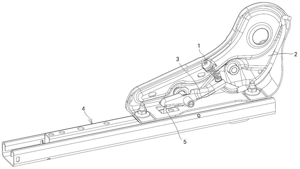
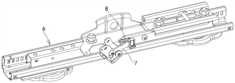
technical field [0001] The invention relates to the technical field of vehicle seats, in particular to an unlocking force and stroke adjustment mechanism. Background technique [0002] Currently, seat comfort adjustments are figure 1 with figure 2 in the way. figure 1 The seat comfort adjustment method shown in is to use a plastic handle to drive the cable 1 to pull the unlocking handle 3 on the seat frame 2 to unlock the slide rail locking mechanism 5 in the slide rail assembly 4. The adjustment range of its unlocking force and unlocking stroke is small, and relevant parts need to be installed on the seat frame, which is not conducive to the modularization of parts. figure 2 The seat comfort adjustment method shown in is to use the plastic handle to drive the unlocking handle 7 on the slide rail assembly 6 to unlock the slide rail locking mechanism 8 in the slide rail assembly 6. The adjustment range of the unlocking force and the unlocking stroke is small, and additi...

Claims


Application Information

Patent Timeline
Patent Type & Authority Patents(China)
IPC IPC(8): B60N2/08B60N2/07B60N2/90
CPCB60N2/08B60N2/0722B60N2/919B60N2002/952
Inventor 付文金黄彬刘珂刘东尤胜
Owner KEIPER (CHANGSHU) SEATING MECHANISMS CO LTD
Learn More