
Anti-toppling and anti-leakage vehicle-mounted garbage can for new energy vehicle

A new energy vehicle, anti-dumping technology, applied in special positions of vehicles, vehicle parts, transportation and packaging, etc., can solve the problem of easy dumping of vehicle-mounted trash cans, and achieve the effect of enhancing anti-dumping ability and ensuring normal driving.

Active Publication Date: 2020-12-15
湖州泰益智能科技有限公司
View PDF6 Cites 2 Cited by
  • Summary
  • Abstract
  • Description
  • Claims
  • Application Information

AI Technical Summary

Problems solved by technology

[0005] The purpose of the present invention is to solve the problem that the vehicle-mounted trash can is easy to dump, and to provide a vehicle-mounted trash can for new energy vehicles that is not easy to dump and prevents garbage from being thrown when dumped.

Method used


Image

  • Anti-toppling and anti-leakage vehicle-mounted garbage can for new energy vehicle
  • Anti-toppling and anti-leakage vehicle-mounted garbage can for new energy vehicle
  • Anti-toppling and anti-leakage vehicle-mounted garbage can for new energy vehicle

Examples


Embodiment 1

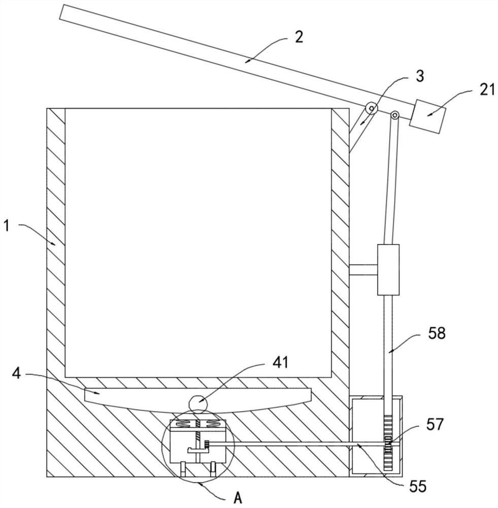
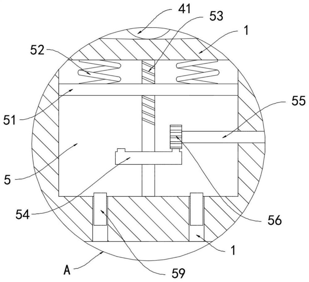
[0024] Such as Figure 1-2 As shown, a vehicle-mounted garbage can for new energy vehicles that prevents dumping and leakage includes a cylinder body 1 and a cover body 2. A support rod 3 is fixedly connected to the side wall of the upper end of the cylinder body 1, and the upper end of the cover body 2 and the support rod 3 Rotational connection, the end of the cover body 2 closer to the support rod 3 is fixedly connected with a counterweight 21, and the counterweight 21 makes the weight of the two ends of the cover body 2 farther from the support rod 3 and closer to the same, similar to the structure of a seesaw , the cover body 2 rotates around the support rod, the bottom of the cylinder body 1 is provided with a sliding chamber 4, the lower part of the sliding chamber 4 is provided with a transmission chamber 5, and the bottom surface of the sliding chamber 4 is arranged in a downwardly concave arc shape. 4 is provided with the magnetic ball 41 that can roll freely.

[00...

Embodiment 2

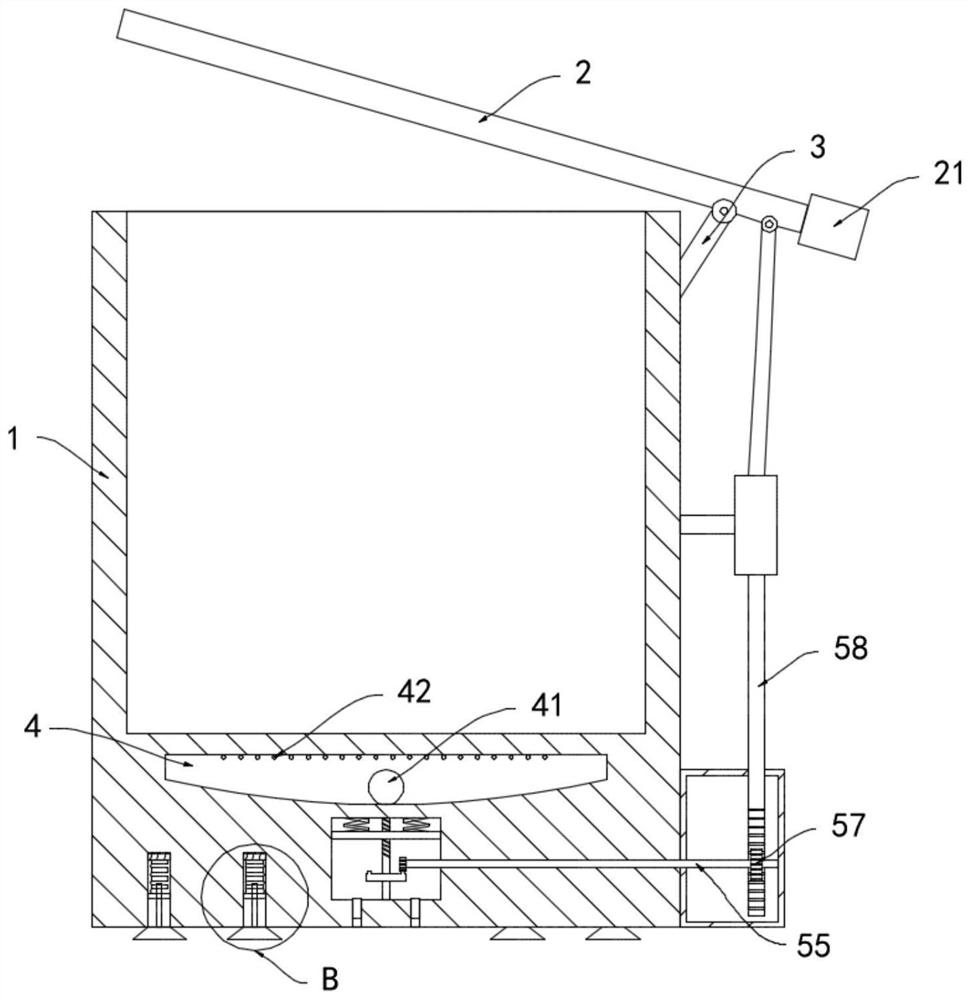
[0032] Such as Figure 3-4 As shown, the difference between this embodiment and Embodiment 1 is that: the top surface of the sliding cavity 4 is fixed with an induction coil 42, and the bottom surface of the cylinder 1 is provided with a plurality of grooves 6, and the plurality of grooves 6 are evenly distributed in the cylinder. At the bottom of the body 1, a sucker 61 is fixedly connected to the opening of the groove 6, an electromagnet 62 is fixedly connected to the top surface of the groove 6, and a helical coil 63 is wound around the electromagnet 62, and the helical coil 63 is electrically connected to the induction coil 42 The lower end of the electromagnet 62 is fixedly connected with a magnet block 65 through an elastic bellows 64, and the magnet block 65 is slidingly connected with the side wall of the groove 6, and the elastic bellows 64 communicates with the inside of the suction cup 61 through an air duct 66.

[0033] In this embodiment, when the vehicle is accel...


PUM


Abstract

The invention belongs to the field of new energy vehicles, and particularly relates to an anti-toppling and anti-leakage vehicle-mounted garbage can for a new energy vehicle. The anti-toppling and anti-leakage vehicle-mounted garbage can comprises a barrel and a cover body, a support rod is fixedly connected to the side wall of the upper end of the barrel, the cover body is rotatably connected with the upper end of the support rod, a sliding cavity is formed at the bottom of the barrel, and a transmission cavity is formed below the sliding cavity; and the bottom face of the sliding cavity is in a downwards-concave cambered surface shape, a magnetic ball capable of rolling freely is arranged in the sliding cavity, a horizontally-arranged lifting plate is connected to the side wall of the transmission cavity in a sliding manner, and the upper end of the lifting plate is fixedly connected with the top face of the transmission cavity through a spring. The lifting plate is made of a magnetic material and is in heteropole attraction with the magnetic ball. The cover body can be automatically closed when the barrel topples over, the situation that garbage and sewage in the barrel are thrown out, and sanitation in the vehicle is affected is avoided, meanwhile, when the vehicle accelerates or decelerates, negative pressure is formed in a suction cup, and the toppling prevention capacityof the barrel is greatly enhanced.

Description

technical field [0001] The invention belongs to the field of new energy vehicles, and in particular relates to a vehicle-mounted trash can for new energy vehicles that prevents dumping and leakage. Background technique [0002] New energy vehicles are non-petroleum fuel vehicles that use batteries instead of conventional power sources. They have the advantages of low noise, low emissions, and high energy efficiency. Most of them are equipped with vehicle-mounted trash cans, which are used to hold garbage and sundries, effectively solving the hazards caused by throwing objects on the windows. [0003] Most of the traditional vehicle-mounted trash cans are not equipped with a lid and the body of the trash can is not fixed for the convenience of driving. However, there will inevitably be road conditions that require deceleration and acceleration during driving. Under the action of inertial force, the vehicle-mounted trash can is very easy to dump. Cause rubbish, sewage in the ...

Claims


Application Information

Patent Timeline
Patent Type & Authority Applications(China)
IPC IPC(8): B60N3/08
CPCB60N3/08
Inventor 顾海明
Owner 湖州泰益智能科技有限公司
Learn More