
Resistor with resistor monomers capable of being connected in series or in parallel

A technology of resistors and resistors, applied in the direction of non-adjustable metal resistors, resistors, resistor sets, etc., can solve the problems of poor heat dissipation, unstable mechanical strength structure, and large volume.

Pending Publication Date: 2020-12-15
山东大通电阻器科技有限公司
View PDF0 Cites 2 Cited by
  • Summary
  • Abstract
  • Description
  • Claims
  • Application Information

AI Technical Summary

Problems solved by technology

[0002] In the current prior art, a resistor includes a frame, several resistor sheets, input terminals, output terminals and center tap terminals, the frame includes a top insulating board, a bottom insulating board and side insulating boards, a bottom insulating board and a top insulating board There are several guide holes on the board; the lower end of the connection between the first resistor sheet and the adjacent middle resistor sheet has a guide post, the connection between the upper end and the lower end of the adjacent middle resistor sheet has a guide post, and the tail resistor sheet is connected to the adjacent There is a guide column at the lower part of the connection of the middle resistance piece; the guide column at the upper end of the connection of two adjacent middle resistance pieces passes through the guide hole and is fixedly connected with the center tap terminal. The problem of the high-power resistance unit device is: large volume, heat dissipation Poor, and the mechanical strength structure is unstable

Method used


Image

  • Resistor with resistor monomers capable of being connected in series or in parallel
  • Resistor with resistor monomers capable of being connected in series or in parallel
  • Resistor with resistor monomers capable of being connected in series or in parallel

Examples


Embodiment Construction

[0030] The present invention will be further described below in conjunction with the accompanying drawings.

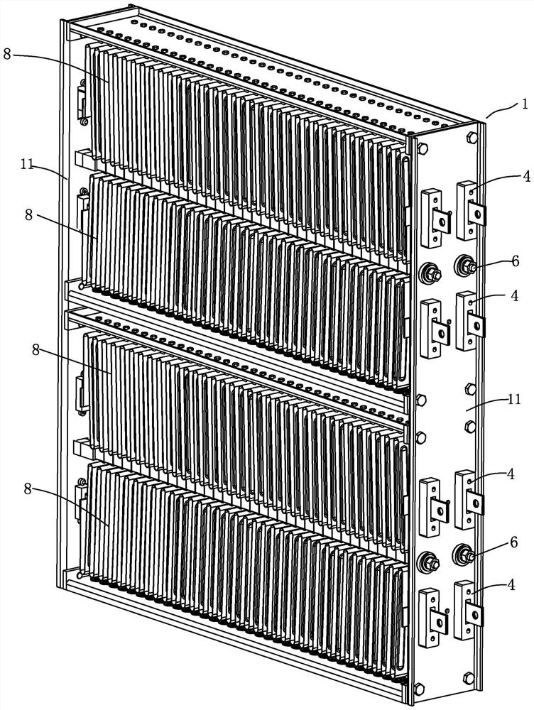
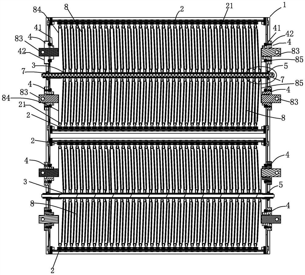
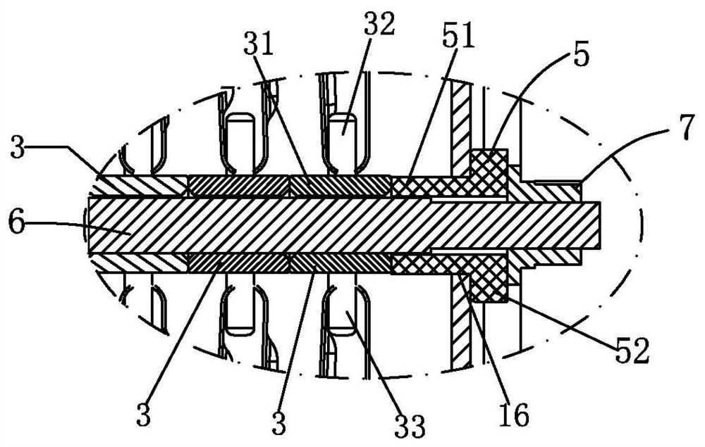
[0031] Such as figure 1 As shown, a resistor whose resistance monomers can be connected in series or in parallel, it includes a square frame-shaped frame 1, an insulating seat 2, an intermediate insulating seat 3, a terminal insulating seat 4, an insulating connecting seat 5, and screw rods at both ends The square connecting rod 6, the nut 7 and several resistor monomers 8,

[0032] Seat frame 1 comprises side frame plate 11, top horizontal frame plate 12 and bottom horizontal frame plate 13, top horizontal frame plate 12 and bottom horizontal frame plate 13 constitute frame plate group; Side frame plate 11 is provided with top connection hole 14, rectangular Terminal seat holes 15, square seat holes 16 and bottom connection holes 17, the top connection hole 14 is a hole for fixing the top horizontal frame plate 12, and the bottom connection hole 17 is a hole for fixi...


PUM


Abstract

The invention relates to a resistor with resistor monomers capable of being connected in series or in parallel, and the resistor comprises a square frame-shaped seat frame, an insulating seat, a middle insulating seat, a terminal insulating seat, an insulating connecting seat, a square connecting rod with screw rods at two ends, a nut and a plurality of resistor monomers, wherein a resistor groupis disposed between a top transverse frame plate and the square connecting rod; the pin columns of the insulating seats on the top transverse frame plate are inserted into the wave crest holes of theresistor single bodies, and the upper pin bodies of the middle insulating seats are inserted into the wave trough holes; the other resistor group is arranged between the square connecting rod and thebottom transverse frame plate, the lower pin body is inserted into the trough hole of the resistor monomer, and the pin body of the insulating seat on the bottom transverse frame plate is inserted into the crest hole; a terminal plate of the resistor monomer extends out of a terminal plate hole of the terminal insulating seat; and the resistor monomers are distributed in rows and columns. Due to the adoption of the structure, the resistor single bodies adopt the distribution mode, the size is reduced, and the resistor single bodies are formed by bending the battens, so the heat dissipation performance is good; one row of resistor monomers can be connected in parallel, and the same column of resistor monomers can be connected in series.

Description

technical field [0001] The present invention relates to a resistor. Background technique [0002] In the current prior art, a resistor includes a frame, several resistor sheets, input terminals, output terminals and center tap terminals, the frame includes a top insulating board, a bottom insulating board and side insulating boards, a bottom insulating board and a top insulating board There are several guide holes on the board; the lower end of the connection between the first resistor sheet and the adjacent middle resistor sheet has a guide post, the connection between the upper end and the lower end of the adjacent middle resistor sheet has a guide post, and the tail resistor sheet is connected to the adjacent There is a guide column at the lower part of the connection of the middle resistance piece; the guide column at the upper end of the connection of two adjacent middle resistance pieces passes through the guide hole and is fixedly connected with the center tap termina...

Claims


Application Information

Patent Timeline
IPC IPC(8): H01C1/08H01C7/00H01C1/14
CPCH01C1/08H01C7/001H01C1/14
Inventor 王爱民
Owner 山东大通电阻器科技有限公司
Learn More