
Miniaturized PCB relay

A relay, L-shaped technology, applied in the direction of relays, electromagnetic relays, detailed information of electromagnetic relays, etc., can solve problems that affect the stability of relay parameters, reduce the pressure of static springs at the normally closed end, and affect the electrical life of products, etc., to achieve effective improvement The effects of magnetically permeable area, avoiding jitter, and avoiding magnetic saturation problems

Pending Publication Date: 2020-12-15
XIAMEN HONGFA AUTOMOTIVE ELECTRONICS
View PDF0 Cites 0 Cited by
  • Summary
  • Abstract
  • Description
  • Claims
  • Application Information

AI Technical Summary

Problems solved by technology

However, when the thickness of the armature increases, the weight of the armature will also increase accordingly. When the weight of the armature increases and the relay operates, the contact kinetic energy between the moving contact and the static contact increases. , thereby affecting the electrical life of the product
In order to solve the problem of vibration when the product is pulled in, the method adopted in the prior art is to directly flatten the head of the armature to reduce the weight of the armature. The support position will be displaced away from the moving contact, which will cause the pressure of the static spring at the normally closed end to decrease, thus affecting the stability of the relay parameters

Method used


Image

  • Miniaturized PCB relay
  • Miniaturized PCB relay
  • Miniaturized PCB relay

Examples


Embodiment

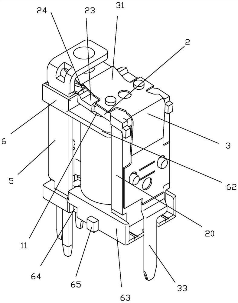
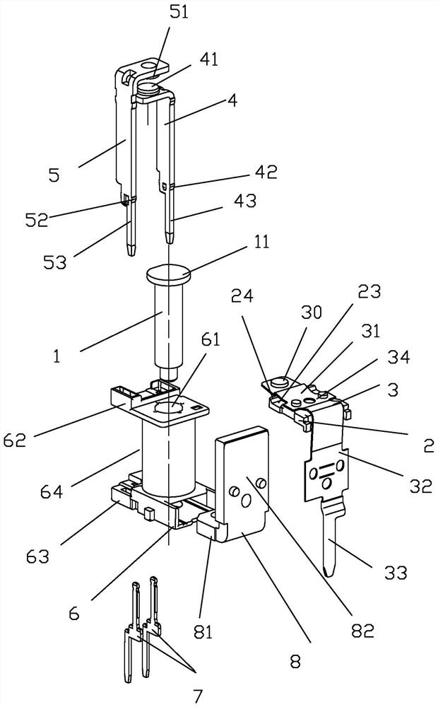
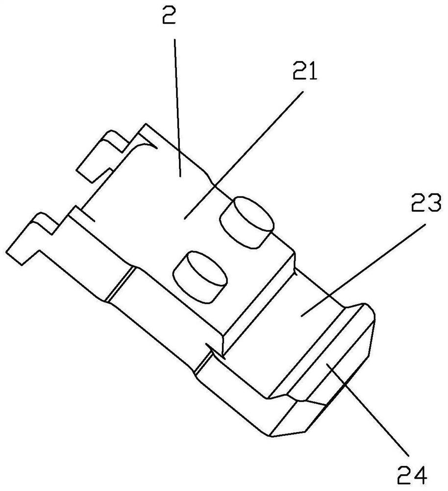
[0043] see Figure 1 to Figure 19 As shown, a miniaturized PCB relay of the present invention includes an iron core 1, an armature 2, a moving reed 3, a static spring normally open end 41 and a static spring normally closed end 51; the root of the swingable part 31 of the moving reed 3 34 is fixed in one side 21 of the armature 2 and makes the other side 22 of the armature 2 and the pole surface 11 of the iron core 1 be in the position of corresponding cooperation; Position) is equipped with a movable contact 30 and fits between the normally open end 41 of the static spring and the normally closed end 51 of the static spring respectively, and the normally open end 41 of the static spring is located on the pole surface 11 of the moving reed 3 facing the iron core 1 On this side of the static spring, the normally closed end 51 of the static spring is located on the side of the pole face of the moving reed 3 facing away from the iron core; 31 is provided with a groove 23 between...


PUM


Abstract

The invention discloses a miniaturized PCB relay. The relay comprises an iron core, an armature, a movable reed, a static spring normally open end and a static spring normally closed end. wherein a root part of a swingable part of the movable contact spring is fixed in one surface of the armature, and the other surface of the armature and the pole surface of the iron core are positioned at a corresponding matching position; a movable contact is arranged at the tail end of the swinging part of the movable contact spring and is respectively matched between the normally open end of the static spring and the normally closed end of the static spring; and in one surface of the armature, a groove is arranged between a fixed position corresponding to the root part of the swinging part of the movable contact spring and the movable contact of the movable contact spring and corresponds to the position of the pole surface of the iron core. According to the relay, the weight of the armature can bereduced on the basis of ensuring the effective magnetic conduction area of the armature so as to avoid the shaking problem generated when the normally open end contact is closed, and the pressure of the normally closed end contact can also be ensured so as to ensure stability of relay parameters.

Description

technical field [0001] The invention relates to the technical field of relays, in particular to a miniaturized PCB relay. Background technique [0002] A PCB relay is a relay for mounting on a PCB (ie, a printed circuit board). Due to the limited mounting space on the PCB, the volume of the PCB relay is usually designed to be small. With the continuous advancement of relay miniaturization, the installation area of ​​PCB relays has become smaller and smaller, and the area of ​​the armature has also become smaller. In order to ensure sufficient product suction, and to ensure the effective magnetic area of ​​the armature, to avoid magnetic saturation , so it is necessary to increase the thickness of the armature. However, when the thickness of the armature increases, the weight of the armature will also increase accordingly. When the weight of the armature increases, the contact kinetic energy between the moving contact and the static contact will increase. When the normally o...

Claims


Application Information

Patent Timeline
Patent Type & Authority Applications(China)
IPC IPC(8): H01H50/30H01H50/24H01H50/54H01H50/56H01H50/14H01H50/44H01H50/36
CPCH01H50/14H01H50/24H01H50/30H01H50/36H01H50/44H01H50/443H01H50/54H01H50/56H01H2050/446
Inventor 吴锦书陈红波
Owner XIAMEN HONGFA AUTOMOTIVE ELECTRONICS
Learn More