
Method for reducing destructive power of lightning stroke low-voltage line, lightning protection device and low-voltage line lightning protection system

A low-voltage line, lightning protection system technology, applied in the installation of cables, installation of lighting conductors, effective triggering of discharge, etc., can solve problems such as poor lightning protection effect, reduce damage, reduce material costs, and reduce material costs and labor. cost effect

Inactive Publication Date: 2020-12-15
PINGDINGSHAN POWER SUPPLY ELECTRIC POWER OF HENAN +2
View PDF5 Cites 0 Cited by
  • Summary
  • Abstract
  • Description
  • Claims
  • Application Information

AI Technical Summary

Problems solved by technology

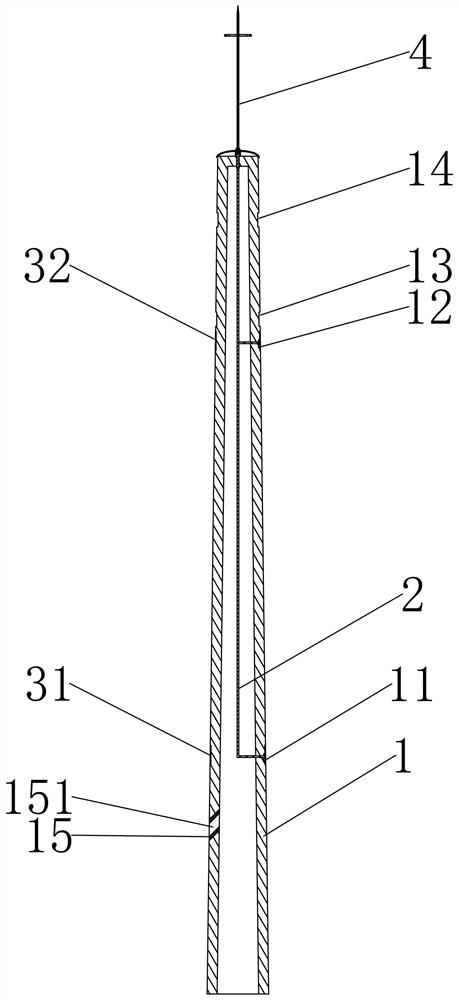
[0004] The object of the present invention is to provide a method for reducing the destructive power of lightning strikes on low-voltage lines, a lightning protection device, and a low-voltage line lightning protection system, so as to solve the technical problem of poor lightning protection effect of existing low-voltage transmission lines without lightning protection lines

Method used


Image

  • Method for reducing destructive power of lightning stroke low-voltage line, lightning protection device and low-voltage line lightning protection system
  • Method for reducing destructive power of lightning stroke low-voltage line, lightning protection device and low-voltage line lightning protection system
  • Method for reducing destructive power of lightning stroke low-voltage line, lightning protection device and low-voltage line lightning protection system

Examples


Embodiment Construction

[0027] The present invention will be described in the form of embodiments below in conjunction with the accompanying drawings, so as to assist those skilled in the art to understand and realize the present invention. Unless otherwise stated, the following embodiments and technical terms therein should not be understood without departing from the background of technical knowledge in this technical field.

[0028] The method for reducing the destructiveness of low-voltage lines struck by lightning according to the present invention is applied to a transmission line composed of at least two towers and three-phase transmission lines suspended on the towers, comprising the following steps:

[0029] Electrically connect the line arrester and the grounding wire, and set the line arrester so that it cooperates with the transmission line to form a line arrester module;

[0030] An upward leading discharge conductor is arranged at a position higher than the transmission line, and the up...


PUM


Abstract

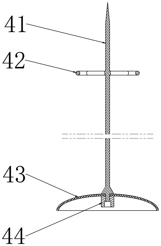
A method for reducing destructive power of a lightning stroke low-voltage line is used for being applied to a power transmission line composed of at least two towers and a three-phase power transmission line and comprises the steps that a line lightning arrester and a grounding wire are electrically connected, and the line lightning arrester is arranged to be matched with the power transmission line to form a line lightning protection module; an uplink pilot discharge conductor is arranged at a position higher than the power transmission line and the uplink pilot discharge conductor and a grounding wire are electrically connected. The lightning protection device comprises a connecting wire, a grounding electrode, the uplink pilot discharge conductor and the line lightning arrester, and thetop end of the uplink pilot discharge conductor is arranged at a position higher than a power transmission line, so that the grounding line to which the uplink pilot discharge conductor belongs formsan uplink pilot discharge module; and the line lightning arrester is arranged at a position matched with the power transmission line, so that the grounding line to which the line lightning arrester belongs forms a line lightning protection module between two adjacent uplink pilot discharge conductors. The low-voltage line lightning protection system comprises a power transmission line and a lightning protection device. And the damage degree of lightning stroke to the power transmission line and equipment connected with the power transmission line can be reduced.

Description

technical field [0001] The invention relates to the field of lightning protection for transmission lines, in particular to a method for reducing the destructive force of lightning strikes on low-voltage lines, a lightning protection device, and a low-voltage line lightning protection system. Background technique [0002] Most low-voltage lines in counties except cities do not have lightning protection lines, but there are lightning protection needs in some areas. In such areas, neutral arc suppression coils or line arresters are often used as lightning protection measures. The dissertation "Research on Lightning Protection Technology of Luohe Distribution Network Lines" written by Li Zhijuan introduced and studied the lightning protection needs and possible lightning protection measures faced by Luohe distribution network in detail. [0003] The patent document CN203160802U describes a grounding integrated concrete pole adopting a fully built-in grounding electrode, includin...

Claims


Application Information

Patent Timeline
IPC IPC(8): H02G13/00
CPCH02G13/20H02G13/40H02G13/80
Inventor 杨海峰李卫东李晓娜任昊李毅华梁国勋李磊刘卓娅杨磊明何丹丹邱丽娟李鹏飞
Owner PINGDINGSHAN POWER SUPPLY ELECTRIC POWER OF HENAN
Learn More