Combined steel pipe straightening roller and straightening device thereof

A straightening and component technology, applied in the field of steel pipe straightening, can solve the problems of fixed range and inability to adjust, and achieve the effect of expanding the range, easy assembly, and convenient individual processing.

Inactive Publication Date: 2020-12-18
杭州嘉威机械配件有限公司
View PDF5 Cites 2 Cited by
  • Summary
  • Abstract
  • Description
  • Claims
  • Application Information

AI Technical Summary

Problems solved by technology

[0004] The above-mentioned patent has the following disadvantages: although the two-curve structure of the straightening roller can be used to straighten steel pipes with different diameters, the straightening roller

Method used


Image

  • Combined steel pipe straightening roller and straightening device thereof
  • Combined steel pipe straightening roller and straightening device thereof
  • Combined steel pipe straightening roller and straightening device thereof

Examples


Embodiment 1

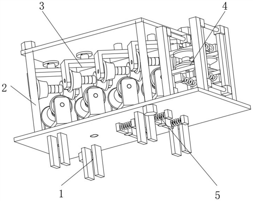
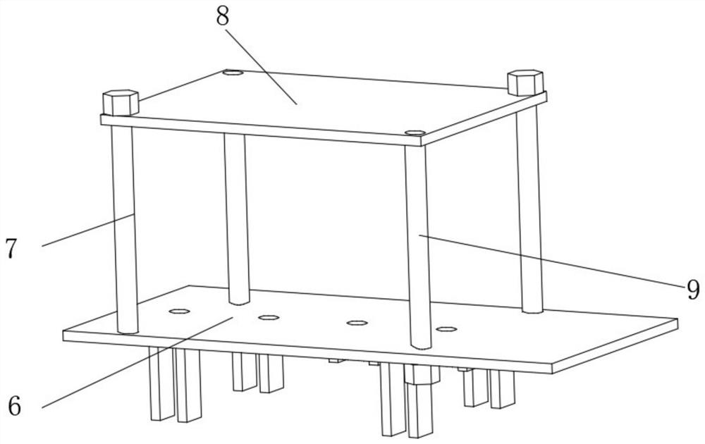
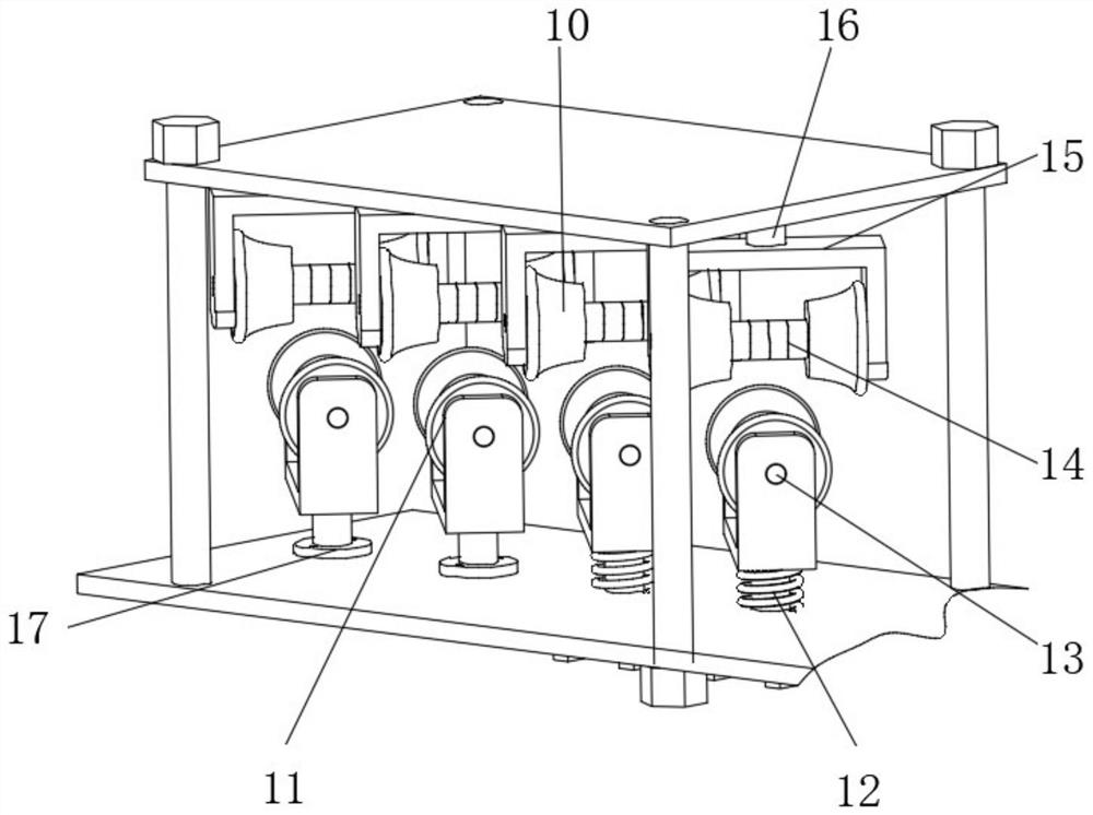
[0036] Straightening devices such as figure 1 , 2As shown, it includes an adjustable frame structure 2 fixed to the ground through the legs 1. The adjustable frame structure 2 includes a base 6 and a top plate 8. The diagonal inner wall of the top plate 8 is threaded with a first screw 7. The other diagonal inner wall of the top plate 8 is rotatably connected with a second screw 9, the bottom inner wall of the first screw 7 is in contact with the top exterior of the base 6, and the other side outer wall of the second screw 9 is threadedly connected. On the inner wall of the base 6, the top of the base 6 and the bottom outer wall of the top plate 8 are provided with a straightening mechanism 3, the top outer wall of the base 6 is provided with a conveying mechanism 4, and the bottom outer wall of the base 6 is provided with a front-end limiting mechanism 5. In this embodiment, put the bending plane of the steel pipe parallel to the vertical plane into the conveying mechanism 4...

Embodiment 2

[0042] Combined steel pipe straightening rollers, such as Image 6 , 7 As shown, it is the straightening roller 14 in Embodiment 1, which specifically includes a first roll block 30, a second roll block 31 and a rotating shaft 34, and the surfaces of the first roll block 30 and the second roll block 31 are all processed with Hyperboloid surface, the outer wall of the opposite side of the first roller block 30 and the second roller block 31 is provided with an adjusting pad 35, and the inner wall of the first roller block 30 and the second roller block 31 is provided with a first keyway 36, The inner wall of the adjusting spacer 35 is provided with a second keyway 37, and the rotating shaft 34 cooperates with the first keyway 36 and the second keyway 37 through the protrusion 33 provided thereon. The first roller block 30, the second The inner walls of the roller block 31 and the adjusting cushion block 35 are all provided with through holes, and the inner walls of the through...


PUM


Abstract

The invention discloses a combined steel pipe straightening roller and a straightening device thereof, and relates to the technical field of steel pipe straightening. The invention aims to solve the problem of range adjustability. The combined type steel pipe straightening roller specifically comprises an adjustable frame structure fixed to the ground through supporting legs, the adjustable framestructure comprises a base and a top plate, first screws are connected to the inner walls of the opposite corners of the top plate through threads, and second screws are rotatably connected to the inner walls of the other opposite corners of the top plate; and the inner walls of the bottoms of the first screws make contact with the outer portion of the top of the base. According to the combined steel pipe straightening roller and the straightening device thereof, by hyperbolic surface structures of first roller blocks and second roller blocks, the range of the pipe diameter of a straightened steel pipe can be guaranteed; and adjusting cushion blocks are arranged between the first roller blocks and the second roller blocks, and the distances between the first roller blocks and the second roller blocks can be adjusted by adjusting the number of the adjusting cushion blocks between the first roller blocks and the second roller blocks, so that the pipe diameter range of the straightened steel pipe is changed, and the range of the straightened steel pipe is expanded.

Description

technical field [0001] The invention relates to the technical field of steel pipe straightening, in particular to a combined steel pipe straightening roller and a straightening device thereof. Background technique [0002] During the processing of steel pipes, the straightening mechanism is an important equipment in steel production. It is used to straighten uneven materials produced in heat treatment or other processes. Steel pipe bending is very important to product quality and directly affects the quality of the pipeline. Normal use. [0003] After searching, the Chinese patent application number is CN207103485U, which discloses a steel pipe straightening machine, including a straightening machine. The straightening machine is provided with a press for straightening steel pipes. The straightening at the bottom projection of the press is The surface of the machine is provided with a T-shaped slot with an upward opening, and an I-shaped steel is arranged inside the T-shape...

Claims


Application Information

Patent Timeline
IPC IPC(8): B21D3/02B21D43/00B21D43/08
CPCB21D3/02B21D43/006B21D43/08
Inventor 程攀
Owner 杭州嘉威机械配件有限公司
Why Eureka
Try Eureka