

Gantry press
A press and gantry technology, applied in the field of presses, can solve problems such as manpower consumption, and achieve the effect of reducing manpower, reducing labor, and feeding materials easily
- Summary
- Abstract
- Description
- Claims
- Application Information
AI Technical Summary
Problems solved by technology
Method used
Image

Examples
Embodiment Construction
[0050] The present invention will be described in further detail below in conjunction with the accompanying drawings.
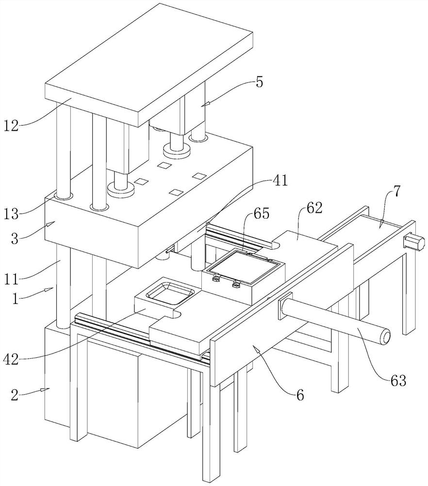
[0051] The embodiment of the present application discloses a gantry press. refer to figure 1 , The gantry press includes a frame 1, a base 2, a lifting seat 3, a main lifting mechanism and a transfer device 6.
[0052] The frame 1 is vertically provided with four lifting columns 11 on the top surface of the base 2 and is also provided with a top plate 12 connecting the four lifting columns 11 . The lifting base 3 is vertically slidably mounted on the frame 1, and the lifting base 3 has a through hole for the vertical vertical penetration of the lifting column 11, and a lifting bushing 13 that is slidingly matched with the lifting column 11 is installed at the through hole. Wherein, a stamping lower die 42 is installed at the center of the top surface of the base 2 , and a stamping upper die 41 facing the stamping lower die 42 is fixed on the bottom surface ...
PUM
 Abstract
Description
Claims
Application Information