Fixture for machining shroud of engine blade and machining method of engine blade

An engine blade and processing method technology, applied in metal processing mechanical parts, manufacturing tools, metal processing equipment and other directions, can solve the problem of unguaranteed blade crown quality, shorten the processing process, improve the detection accuracy, and is not easy to twist or the effect of vibration

Active Publication Date: 2020-12-18
AECC AERO SCI & TECH CO LTD
View PDF10 Cites 2 Cited by
  • Summary
  • Abstract
  • Description
  • Claims
  • Application Information

AI Technical Summary

Problems solved by technology

[0007] The object of the present invention is to provide a jig for machining the blade crown of the engine blade and a processing method for the engine blade, so as to solve the problem that the quality of the existing blade crown cannot be guaranteed after processing

Method used


Image

  • Fixture for machining shroud of engine blade and machining method of engine blade
  • Fixture for machining shroud of engine blade and machining method of engine blade
  • Fixture for machining shroud of engine blade and machining method of engine blade

Examples


Embodiment

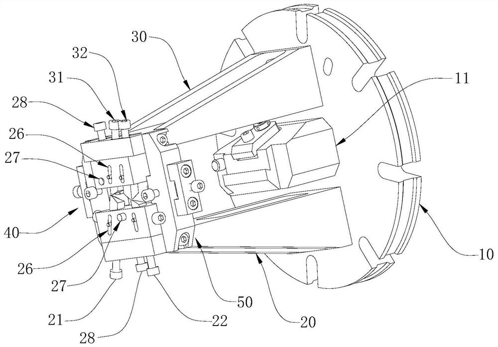
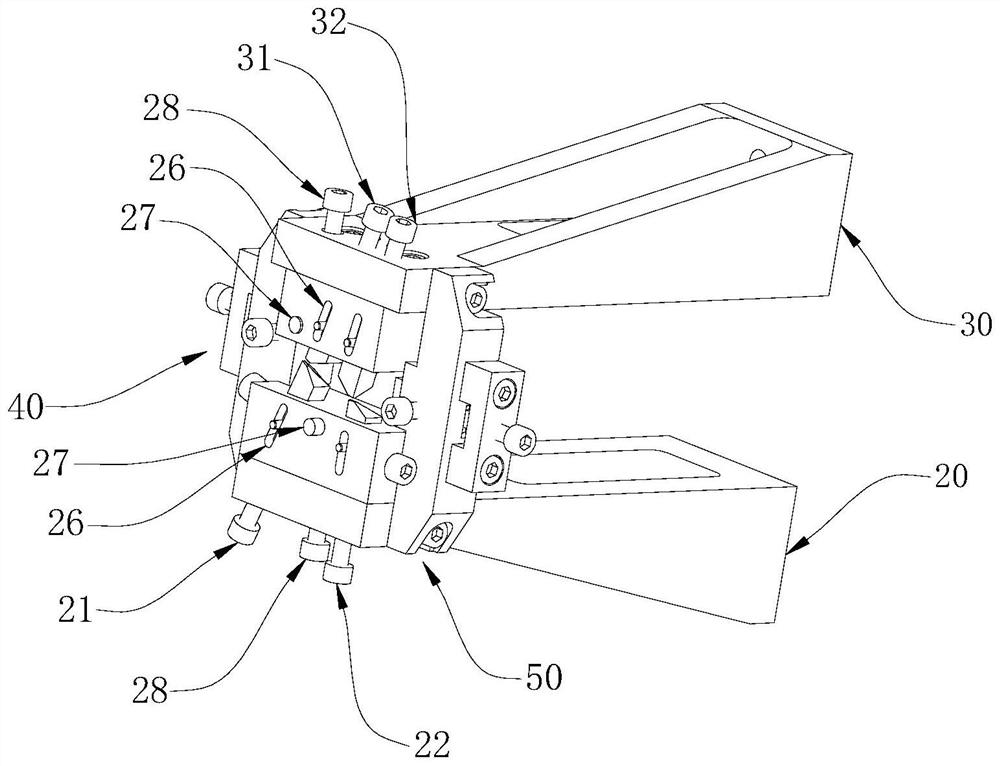
[0052] The jig for machining the crown of the engine blade includes: a first support block 20 and a second support block 30 , the first support block 20 and the second support block 30 are perpendicular to the machine tool positioning plate 10 and installed on the machine tool positioning plate 10 . The structure of the first support block 20 and the second support block 30 is consistent, and the first support block 20 and the second support block 30 are oppositely arranged on both sides of the jaw 11 on the machine positioning plate 10, the first support block 20 and the second support block Each block 30 includes a connecting end connected to the machine tool positioning plate 10 through bolts and a positioning end away from the machine tool positioning plate 10 . The positioning end of the first support block 20 is used to cooperate with the convex surface of the blade airfoil, and the convex surface of the blade airfoil is limited, and the positioning end of the second supp...


PUM


Abstract

The invention discloses a fixture for machining a shroud of an engine blade and a machining method of the engine blade, and belongs to the technical field of aero-engines. The fixture for machining the shroud of the engine blade comprises a first supporting block and a second supporting block which are oppositely arranged, wherein the first supporting block and the second supporting block jointlylimit the position, close to the blade shroud, of a blade body. According to the fixture, an original tip is replaced with a fake tip to clamp and fix the blade, the distance between the shroud and the fake tip is small, the milling rigidity of the blade shroud is good, and the influence brought by cutter relieving and vibration is reduced; meanwhile, the problems that the blade is extruded when the blade shroud is axially located through the tip, and consequently a part deforms and deviates from a locating surface are solved; and the blade shroud has consistency in machining and measuring technical objectives, so that the detection precision is improved, and the machining quality of the blade shroud is reversely ensured.

Description

technical field [0001] The invention relates to the technical field of aero-engines, in particular to a jig for machining a crown of an engine blade and a machining method for the engine blade. Background technique [0002] In order to meet the high-power and high-efficiency requirements of the new generation of aero-engines, blades are the core components. The structure of aero-engines has a breakthrough innovation compared with the old models. Compared with the previous blades, its structure is relatively complex and technical requirements relatively higher. [0003] When processing the blade crown, it has the characteristics of complex structure, poor blade rigidity, large cold deformation, many related dimensions and high technical requirements. The main positioning datum is to withstand the crown of the blade through the tip, and fix it by clamping at both ends, so that the crown of the blade has the following technical defects in the process of processing: [0004] 1...

Claims


Application Information

Patent Timeline
Patent Type & Authority Applications(China)
IPC IPC(8): B23Q3/00B23C3/18
CPCB23Q3/00B23C3/18B23Q2703/10
Inventor 邓明忠唐波张涛孟军
Owner AECC AERO SCI & TECH CO LTD
Why Eureka
Try Eureka