
Controller

A technology of the controller and the control part, which is applied in the field of controllers, can solve problems such as wrong switch status and inability to judge the status of electric actuators, and achieve the effect of suppressing operational failures

Pending Publication Date: 2020-12-18
DENSO CORP
View PDF1 Cites 0 Cited by
  • Summary
  • Abstract
  • Description
  • Claims
  • Application Information

AI Technical Summary

Problems solved by technology

For example, when the controller fails to properly monitor the state of the switch, and then makes a wrong judgment on the state of the switch, the controller cannot properly judge the state of the electric actuator

Method used


Image

  • Controller
  • Controller
  • Controller

Examples


no. 1 approach

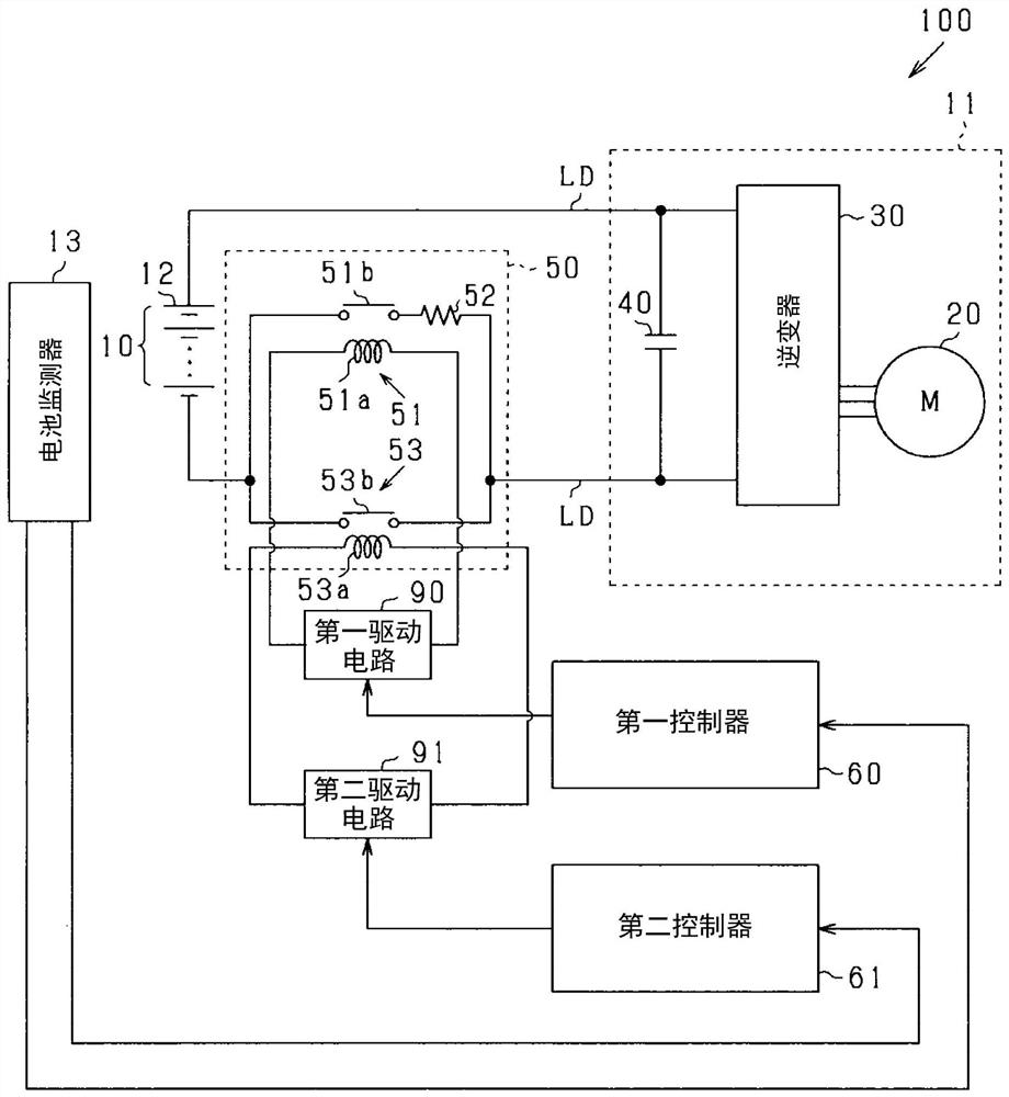
[0025] A first embodiment of the controller of the present disclosure, in which the controller is applied to the vehicle power supply system 100, will now be described with reference to the accompanying drawings.

[0026] Such as figure 1 As shown, the power supply system 100 of the first embodiment includes: a battery 10 as a power supply unit; an electrical load 11 ; an SMR assembly 50 ; a first controller 60 ; and a second controller 61 . The battery 10 is a chargeable and dischargeable battery, specifically, an assembled battery including a plurality of lithium ion batteries 12 connected in series. Battery 10 may be another type of accumulator.

[0027] The electric load 11 includes a rotating armature 20 , an inverter 30 and a smoothing capacitor 40 . The rotating armature 20 is connected to the battery 10 through an inverter 30 . The rotating armature 20 receives electric power from the battery 10 and transmits electric power to the battery 10, so that the rotating ar...

no. 2 approach

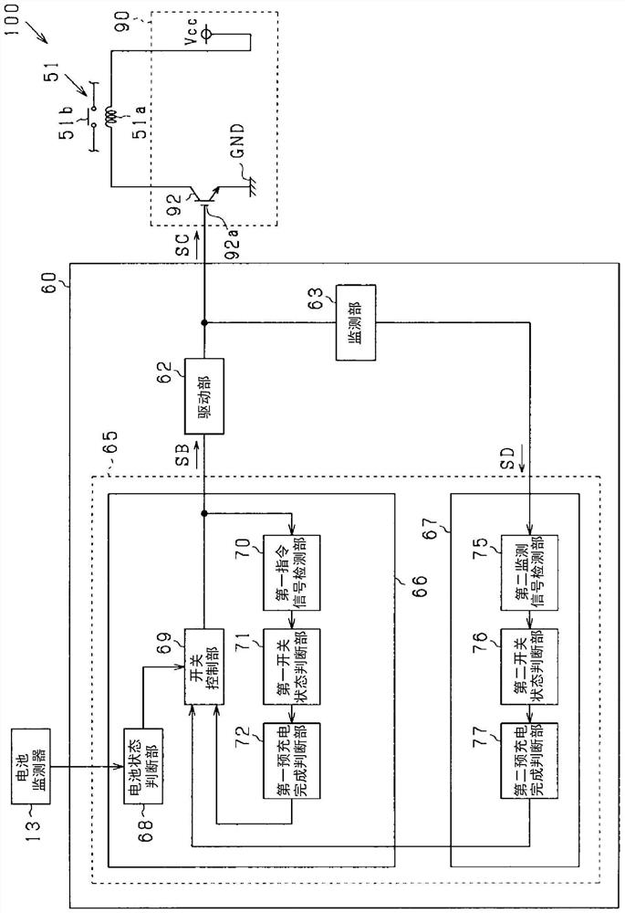
[0066] Below, refer to Figure 4 , Figure 5 (A) and (B) and Image 6 (A) and (B) describe the second embodiment, focusing mainly on differences from the first embodiment. exist Figure 4 , the same reference numerals are assigned to the figure 2 The same processing as the configuration shown in , and repeated descriptions are omitted for convenience.

[0067] Such as Figure 4 As shown, the difference between the second embodiment and the first embodiment is that the first controller 60 includes a cut-off part 64 . The shutoff section 64 receives the shutoff signal SE from the control section 65, and forcibly switches the switch 92 to an off state based on the shutoff signal SE. Specifically, the drive unit 62 has a cutoff switch connected to the electrical path LS connecting the drive unit 62 and the switch 92 . Specifically, the cutoff switch cuts off the drive signal SC output from the drive unit 62 to the electric path LS. When the cut-off signal SE is acquired, ...


PUM


Abstract

A controller (60) for a system includes a first control section (66) and a second control section (67). The system includes an electrical actuator (51), a switch (92) switching the electrical actuatorbetween a power supply state and a power cutoff state, and a drive section (62) driving the switch. The drive section outputs, to the switch, a drive signal (SC) to drive the switch based on a command signal (SB) for switching of the switch. The first control section determines a switch state based on the command signal, and the second control section determines a switch state based on the drivesignal. At least one of the first control section and the second control section determines the electrical actuator to be in the power supply state on the condition that the first control section determines the switch to be in the power supply state, and the second control section also determines the switch to be in the power supply state.

Description

technical field [0001] The present disclosure relates to a controller for a system. Background technique [0002] As described in Japanese Patent Application Laid-Open No. 2016-142141, there is known a controller for controlling a switch that controls electric motors such as linear solenoids and electric motors between a power-on state and a power-off state. The actuator switches. The controller monitors and judges the state of the switch, and judges the state of the electric actuator based on the judgment result of the switch state. [0003] To improve safety, redundancy may be required to judge the status of electric actuators. For example, when the controller fails to properly monitor the state of the switch, and then makes a wrong judgment on the state of the switch, the controller cannot properly judge the state of the electric actuator. Contents of the invention [0004] The present disclosure is made to solve the above-mentioned problems, and an object of the pre...

Claims


Application Information

Patent Timeline
Patent Type & Authority Applications(China)
IPC IPC(8): B60L15/20B60L58/10B60R16/02
CPCB60L15/20B60L58/10B60R16/02H03K17/08122H03K2217/0072Y02T10/70Y02T10/72H01H9/54Y02T10/7072Y02T90/14H03K2217/0081H03K17/08104H03K17/30
Inventor 橘勇树
Owner DENSO CORP
Learn More