A conveying device for mechanical equipment used in electromechanical engineering

A technology of mechanical equipment and conveying device, applied in the direction of mechanical conveyor, conveyor control device, conveyor, etc., can solve the problem of single detection angle, achieve the effect of improving accuracy, improving detection efficiency and effect, and ensuring stability

Active Publication Date: 2022-06-24
萧县奥新农业科技有限公司
View PDF10 Cites 0 Cited by
  • Summary
  • Abstract
  • Description
  • Claims
  • Application Information

AI Technical Summary

Problems solved by technology

[0005] The purpose of the present invention is to solve the problem of single detection angle in the prior art, and propose a conveying device for mechanical equipment used in electromechanical engineering

Method used


Image

  • A conveying device for mechanical equipment used in electromechanical engineering
  • A conveying device for mechanical equipment used in electromechanical engineering
  • A conveying device for mechanical equipment used in electromechanical engineering

Examples


Embodiment 1

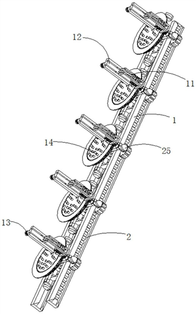
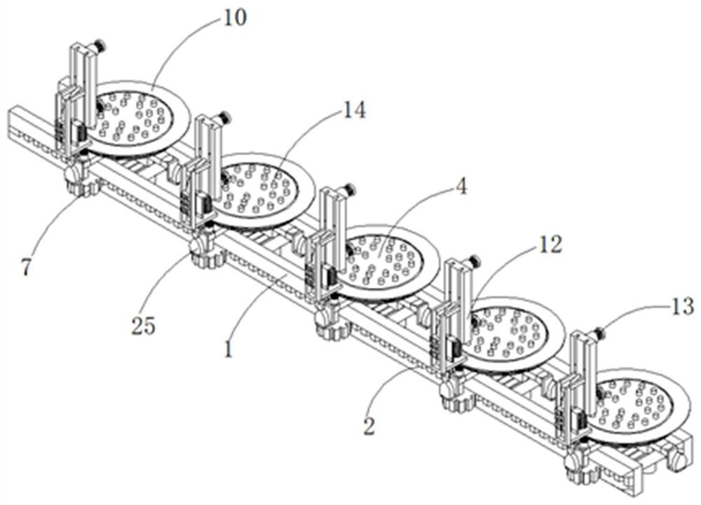
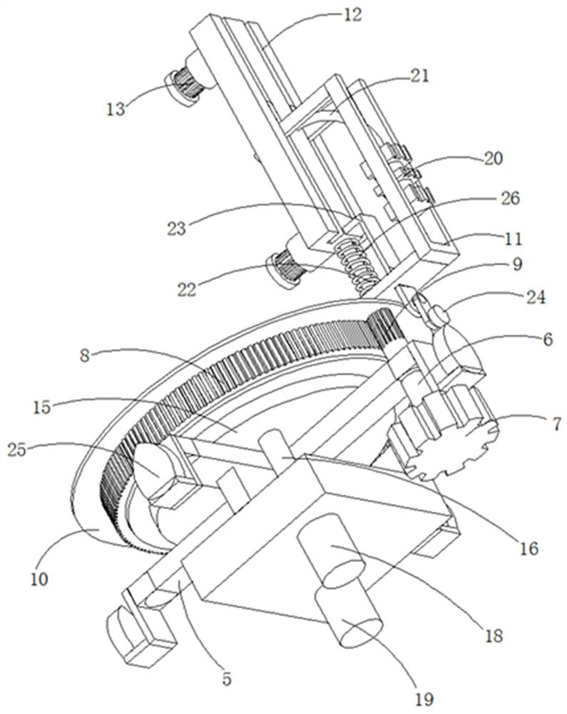
[0038] refer to Figure 1-6 , a conveying device for mechanical equipment for electromechanical engineering, including two linear guide rails 1 symmetrically distributed, the outer side wall of the linear guide rail 1 is fixed with gear teeth 2 evenly distributed along the direction of the linear guide rail 1, and the two linear guide rails are connected between There is a driving rail seat 3, a conveying table 4 is fixed on the driving rail seat 3, a positioning assembly is arranged on the conveying table 4, and the bottom of the conveying table 4 is also fixed with evenly distributed support rods 5, and the support rods 5 are rotatably connected with Rotating rod 6, the bottom end of the rotating rod 6 is fixedly connected with a transmission gear 7 meshing with the gear teeth 2, the outer side of the conveying table 4 is rotatably connected with a gear ring 8 through a bearing, and the top end of the rotating rod 6 is also fixed with a gear ring 8. The meshed driven gear 9,...

Embodiment 2

[0046] refer to Figure 1-6 , a conveying device for mechanical equipment for electromechanical engineering, including two linear guide rails 1 symmetrically distributed, the outer side wall of the linear guide rail 1 is fixed with gear teeth 2 evenly distributed along the direction of the linear guide rail 1, and the two linear guide rails are connected between There is a driving rail seat 3, a conveying table 4 is fixed on the driving rail seat 3, a positioning assembly is arranged on the conveying table 4, and the bottom of the conveying table 4 is also fixed with evenly distributed support rods 5, and the support rods 5 are rotatably connected with Rotating rod 6, the bottom end of the rotating rod 6 is fixedly connected with a transmission gear 7 meshing with the gear teeth 2, the outer side of the conveying table 4 is rotatably connected with a gear ring 8 through a bearing, and the top end of the rotating rod 6 is also fixed with a gear ring 8. The meshed driven gear 9,...


PUM


Abstract

The invention discloses a conveying device for mechanical equipment used in electromechanical engineering and a method for using the same, belonging to the technical field of conveying devices for electromechanical equipment; a conveying device for mechanical equipment used in electromechanical engineering, including two symmetrically distributed linear guide rails, the linear guide rails The outer wall is fixed with gear teeth evenly distributed along the direction of the linear guide rails. A driving rail seat is connected between the two linear guide rails. A conveyor platform is fixedly connected to the drive rail seat. Evenly distributed support rods are fixedly connected, and a rotating rod is connected to the supporting rod. The bottom end of the rotating rod is fixedly connected with a transmission gear meshing with the gear teeth. The outer side of the conveyor table is connected to a gear ring through a bearing. A driven gear meshing with the gear ring is fixedly connected, and an annular fixing plate is fixedly connected to the top of the gear ring, and a support frame is fixedly connected to the outer edge of the top of the ring fixing plate; Multi-angle detection function.

Description

technical field [0001] The present invention relates to the technical field of conveying devices for electromechanical equipment, in particular to a conveying device for mechanical equipment used in electromechanical engineering. Background technique [0002] Mechanical and electrical equipment generally refers to machinery, electrical appliances and electrical automation equipment. It is different from hardware, which refers to finished products that can achieve certain functions. With the continuous improvement of people's living standards, people have more and more needs for electromechanical equipment in their daily life. From transportation to various household appliances, computers, printers, etc., they have become indispensable electromechanical products in people's lives. Advanced electromechanical equipment can not only greatly improve labor productivity, reduce labor intensity, improve production environment, and complete tasks that cannot be completed by manpower...

Claims


Application Information

Patent Timeline
Patent Type & Authority Patents(China)
IPC IPC(8): G01N21/89
CPCB65G47/74B65G35/06B65G43/00
Inventor 魏海虎
Owner 萧县奥新农业科技有限公司
Why Eureka
Try Eureka