
Concrete tube lifting tool and hanging method thereof

A technology of concrete pipes and spreaders, applied in the direction of load hanging components, transportation and packaging, safety devices, etc., can solve the problems of prestressed concrete pipes falling off, low work efficiency, and unstable fixation, so as to avoid shaking and falling, labor The effect of low strength and eliminating potential safety hazards

Pending Publication Date: 2020-12-18
浙江巨龙管业科技有限公司
View PDF8 Cites 0 Cited by
  • Summary
  • Abstract
  • Description
  • Claims
  • Application Information

AI Technical Summary

Problems solved by technology

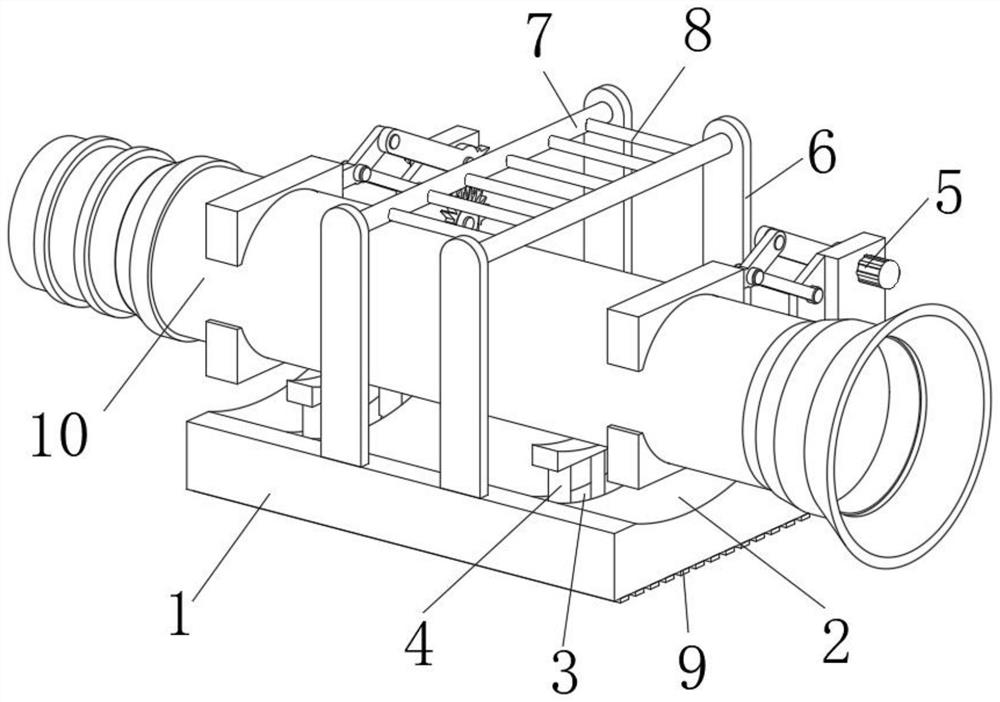
[0003] Usually, all the prestressed concrete pipes are lifted out of the high-temperature steam curing kiln, and an operator works in the high-temperature steam curing kiln for at least 1 hour. This manual operation method has the following potential safety hazards: 1. Operators often suffer from heatstroke when working in high-temperature steam curing kilns in summer, which is labor-intensive and low-efficiency; 2. Since the prestressed concrete pipe is cylindrical, it is easy to shake during the fixing process, and the fixation is not firm During the lifting process, the prestressed concrete pipe will fall off, which will cause the hidden danger of the operator being crushed. Therefore, we have proposed a concrete pipe spreader and its lifting method

Method used


Image

  • Concrete tube lifting tool and hanging method thereof
  • Concrete tube lifting tool and hanging method thereof
  • Concrete tube lifting tool and hanging method thereof

Examples


Embodiment Construction

[0030] In order to make the technical means, creative features, goals and effects achieved by the present invention easy to understand, the present invention will be further described below in conjunction with specific embodiments.

[0031] In the description of the present invention, it should be noted that the terms "upper", "lower", "inner", "outer", "front end", "rear end", "both ends", "one end", "another end" The orientation or positional relationship indicated by etc. is based on the orientation or positional relationship shown in the drawings, and is only for the convenience of describing the present invention and simplifying the description, rather than indicating or implying that the referred device or element must have a specific orientation, use a specific Azimuth configuration and operation, therefore, should not be construed as limiting the invention. In addition, the terms "first" and "second" are used for descriptive purposes only, and should not be understood ...


PUM


Abstract

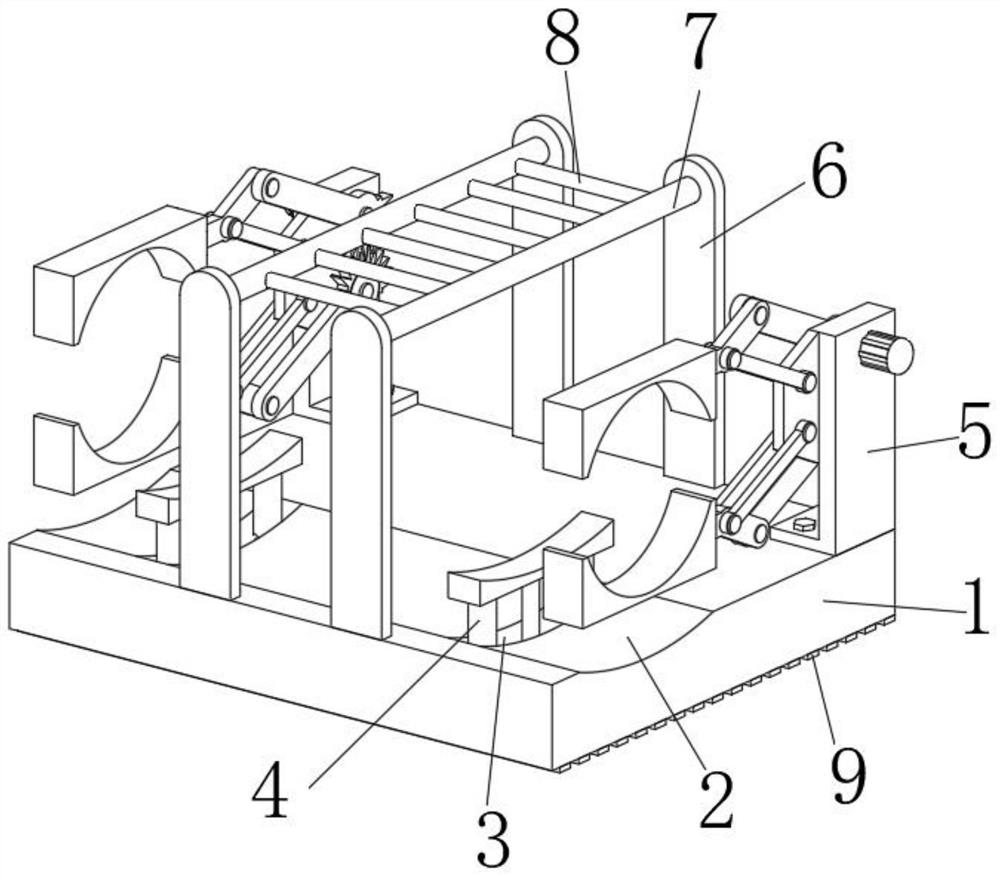
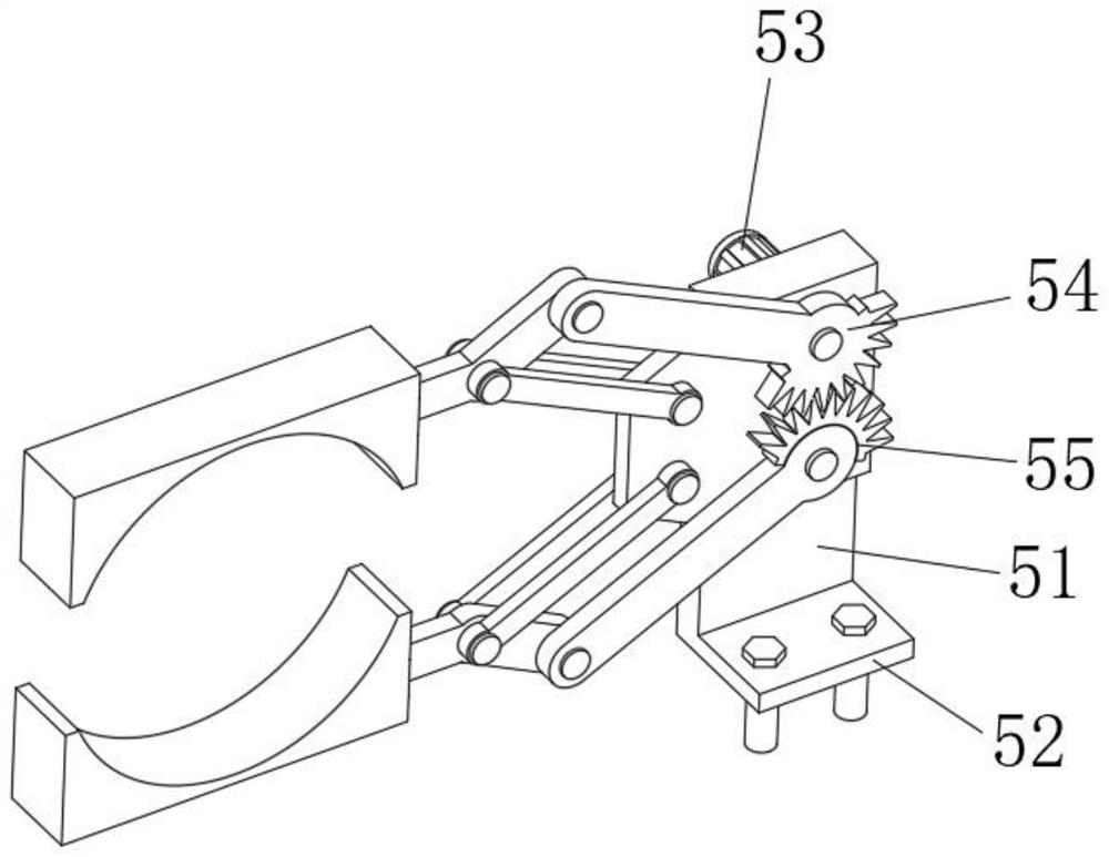
The invention discloses a concrete tube lifting tool. The concrete tube lifting tool comprises a base, wherein an arc-shaped slot I is formed in the left part of the upper end of the base; two storageslots are formed in the lower slot wall of the arc-shaped slot I; one lifting mechanism is arranged in each storage slot; two fixing mechanisms which are positioned at the outer sides of the two lifting mechanisms are fixedly mounted on the right part of the upper end of the base; two lifting plates are fixedly welded on both the left part of the upper end of the base and the right part of the upper end of the base; a longitudinal rod is fixedly co-connected between the two lifting plates on the same horizontal plane left and right; a plurality of transverse rods are welded between the two longitudinal rods; the lower end of the base is fixedly connected to a plurality of rubber strips; a concrete tube main body is fixedly co-connected between the left parts of the fixing mechanisms and the lifting mechanisms such that a concrete tube is lifted by the lifting mechanisms and is further fixed by the fixing mechanisms. The concrete tube lifting tool disclosed by the invention is compactin structure, is strong in stability, is high in degree of automation, adopts a convenient-to-operate lifting method, and avoids potential safety hazards.

Description

technical field [0001] The invention relates to the technical field of concrete pipe processing, in particular to a concrete pipe hanger and a lifting method thereof. Background technique [0002] Prestressed steel cylinder concrete pipe refers to a water pipe made by winding a hoop prestressed steel wire on a high-strength concrete core with a steel cylinder, and then spraying a dense cement mortar protective layer on it. In reality, this Pipes are widely used in main pipeline projects in the fields of urban water supply, drainage, industrial water transmission, irrigation water conservancy, and power plant supply water. In addition, they are also widely used in factory pipe networks, inverted siphons, pressure tunnel pipes, and deep-covered soil culvert pipes. [0003] Usually, all the prestressed concrete pipes are lifted out of the high-temperature steam curing kiln, and an operator works in the high-temperature steam curing kiln for at least 1 hour. This manual operatio...

Claims


Application Information

Patent Timeline
IPC IPC(8): B66C1/44B66C15/00
CPCB66C1/44B66C15/00
Inventor 李均亮吕成杰仲政惟黄丽梅朗亦男
Owner 浙江巨龙管业科技有限公司
Learn More