Disinfection cloth cutting machine and swing mechanism thereof

A technology of cloth cutting machine and swing mechanism, which is applied in the direction of winding strips, sending objects, thin material processing, etc., and can solve problems such as multi-space, large volume, and complexity

Inactive Publication Date: 2021-04-02
浙江德康环保科技有限公司
View PDF0 Cites 0 Cited by
  • Summary
  • Abstract
  • Description
  • Claims
  • Application Information

AI Technical Summary

Problems solved by technology

This type of cutter device requires a large space for installation, and the whole mechanism is relatively large and complicated, which is relatively dangerous. The overall volume of the device is large and takes up too much space

Method used


Image

  • Disinfection cloth cutting machine and swing mechanism thereof
  • Disinfection cloth cutting machine and swing mechanism thereof
  • Disinfection cloth cutting machine and swing mechanism thereof

Examples


Embodiment 1

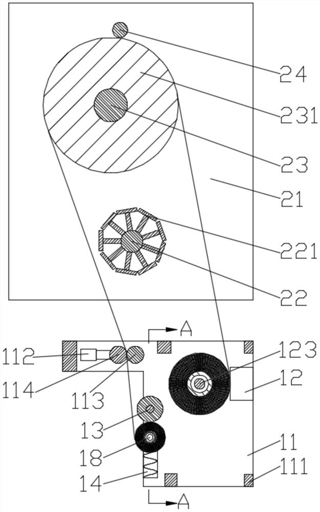
[0030] Such as Figure 1-5 as shown,

[0031] The leveling mechanism includes a pair of mutually symmetrical leveling fixing plates 21, a first leveling shaft 23 and a second leveling shaft 24 are rotated between the leveling fixing plates 21, and a leveling roller is fixed on the first leveling shaft 23 231, the smoothing roller 231 is close to the second smoothing shaft 24;

[0032] The sub-volume mechanism includes a pair of mutually symmetrical sub-volume fixing plates 11, and a plurality of supporting plates 111 are fixedly connected between the sub-volume fixing plates 11;

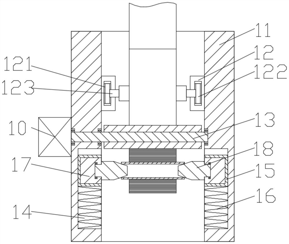
[0033] It includes two sub-volume cylinders 12, and the sub-volume cylinders 12 are respectively fixed on the sides of the sub-volume fixing plate 11 close to each other. The extension ends of the sub-volume cylinders 12 are provided with support grooves 121, and the support grooves Supporting bearings 122 are supported in 121, and the supporting bearings 122 are connected by split shafts 123, and ...

Embodiment 2

[0049] Such as Figure 6 and Figure 7 As shown, the difference between Embodiment 2 and Embodiment 1 is that: a pair of swing plates 27 are symmetrically fixed on the first leveling shaft 22, and the leveling rollers 231 are located between the swing plates 27; A baffle shaft 271 is fixed between the fixed plates 21, and the baffle shaft 271 is used to support the swing plate 27. One of the smooth fixed plates 21 is fixedly connected with a swing motor 20, and the smoothing roller 231 is rotatably arranged on the on the first smoothing roller 23 .

[0050] The difference from the method used in Embodiment 1 is that the swing motor 10 drives the first leveling shaft 23 to rotate, the first leveling shaft 23 drives the swing plate 27 to swing, and the swing plate 27 drives the cutting Shaft 22 swings, and the cutting shaft 22 drives the cutting limiting shaft 221 to swing. When the cutting limiting shaft 211 swings to a suitable position, the saw blade 34 is used to carry out...

Embodiment 3

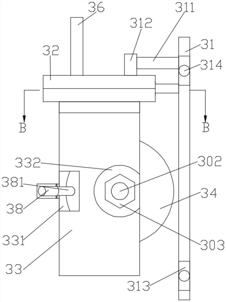
[0052] Such as Figure 8 and Figure 9 As shown, the difference between Embodiment 3 and Embodiment 1 is that: a guide slide plate 25 is fixed between the flat fixing plates 21, and a slide guide groove 26 is provided on the side of the guide slide plate 25 close to the cutting shaft 22 , the sliding guide plate 22 is provided with a through groove, the through groove communicates with the sliding guide groove 26, the connecting plate 32 is fixedly provided with a slider 37, and the sliding block 37 can be connected with the sliding guiding groove 26, the slider 37 can pass through the through groove and enter the guide groove.

[0053] The difference from the method used in Embodiment 1 is: put the slider 37 into the guide chute 26 through the through groove, push the handle 36 to drive the saw blade 34 along the gap between the cutting limit axis 221 For cutting, the slider 37 slides along the slide guide groove 26 .


PUM


Abstract

The invention relates to a disinfection cloth cutting machine and a swing mechanism thereof. The disinfection cloth cutting machine comprises a pair of mutually symmetrical leveling fixing plates, anda first leveling shaft and a second leveling shaft are arranged between the leveling fixing plates in a running fit manner. The disinfection cloth cutting machine also comprises a roll dividing mechanism and a cutting mechanism, and the cutting mechanism comprises a cutting shaft and a cutting tool. A cutting limiting plate is arranged on the cutting shaft, and the cutting tool comprises a saw blade arranged in a protective plate. According to the technical scheme, the cutting tool is separated from other structures and pushed to improve the safety rate during cutting, meanwhile, the saw blade in the cutting tool is located in a protection groove, accidents during use are avoided, the supporting shaft is supported on a pressing plate when the cutting tool is not used, and the saw blade can prevent people from being accidentally injured under the protection of the protective plate and the pressing plate; and the cutting shaft can swing, the position of a cutting point is changed by changing the position of the cutting shaft, and the safety during cutting is improved.

Description

technical field [0001] The invention relates to the field of cutting machines, in particular to a sterile cloth cutting machine and a swing mechanism thereof. Background technique [0002] Disinfection cloths or wet wipes, films, etc. will be flattened during the production process, rolled into the length required by the wrapping knife, and cut off. Present cutting device generally all is arranged on the top of leveling device, and when needing to cut off, cutting knife is pushed down from above and then cuts off. This type of cutter device requires a large space for installation, and the whole mechanism is relatively large and complicated, which is dangerous, and the overall volume of the device is relatively large and takes up too much space. Contents of the invention [0003] In order to solve the above problems, the object of the present invention is to provide a disinfectant cloth cutting machine with compact structure and safe cutting and its swing mechanism. [00...

Claims


Application Information

Patent Timeline
Patent Type & Authority Applications(China)
IPC IPC(8): B65H18/02B65H18/14B65H23/26B65H35/06
CPCB65H18/028B65H18/14B65H23/26B65H35/06B65H2701/10
Inventor 何忠
Owner 浙江德康环保科技有限公司
Why Eureka
Try Eureka