
Color-controllable LED luminescent lamp

A technology of LED filament and LED light source, which is applied in the direction of semiconductor devices, light sources, plane light sources, etc. of light-emitting elements, can solve the problems of difficulty in realizing the free display and switching of various colors, and the single color display method of LED light-emitting lamps.

Pending Publication Date: 2020-12-18
HANGZHOU HANGKE OPTOELECTRONICS
View PDF0 Cites 2 Cited by
  • Summary
  • Abstract
  • Description
  • Claims
  • Application Information

AI Technical Summary

Problems solved by technology

[0005] Based on this, it is necessary to provide a color-controllable LED light-emitting lamp for the problem that the traditional LED light-emitting lamp has a single color display method and it is difficult to realize the free display and switching of multiple colors.

Method used


Image

  • Color-controllable LED luminescent lamp
  • Color-controllable LED luminescent lamp
  • Color-controllable LED luminescent lamp

Examples


Embodiment Construction

[0063] In order to make the purpose, technical solution and advantages of the present application clearer, the present application will be further described in detail below in conjunction with the accompanying drawings and embodiments. It should be understood that the specific embodiments described here are only used to explain the present application, and are not intended to limit the present application.

[0064] The present application provides a color-controllable LED light-emitting lamp.

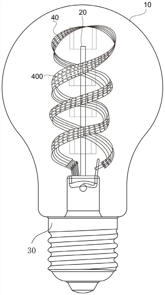
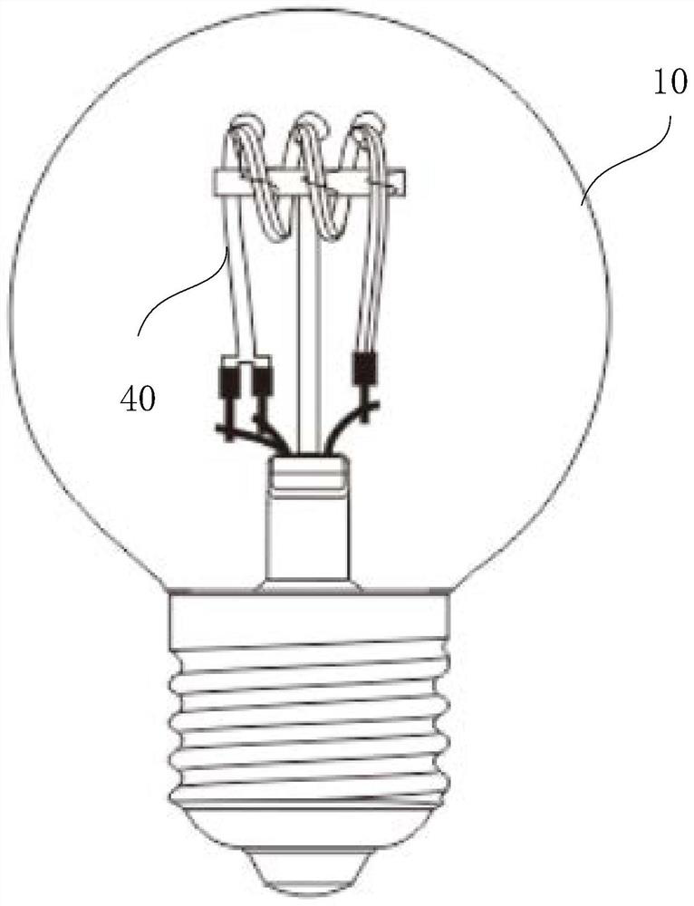
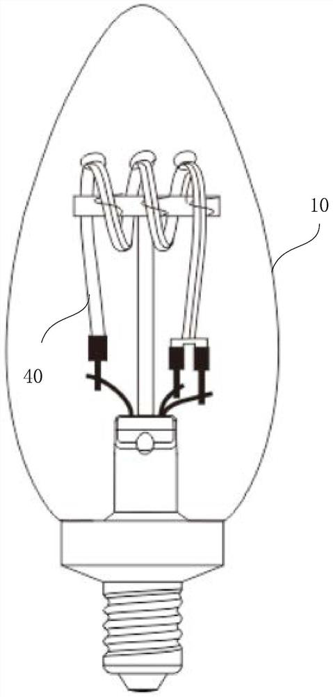
[0065] Such as figure 1 As shown, in an embodiment of the present application, the color-controllable LED light-emitting lamp includes a lampshade 10 , a stem 20 , a lamp cap 30 and at least one LED light source 40 . The stem 20 is fixedly connected with the lampshade 10 . The lamp holder 30 is fixedly connected with the lampshade 10 . Each LED light source 40 is fixedly connected with the stem 20 .

[0066] A plurality of LED chips 400 are arranged in the LED light source 40 . The...


PUM

PropertyMeasurementUnit
widthaaaaaaaaaa

Abstract

The invention relates to a color-controllable LED luminescent lamp. LED light sources are composed of mini-LED chips with the relatively small sizes, so that the number of the LED light sources capable of being contained in a lampshade is increased, the whole LED luminescent lamp can show more color types, and free showing and switching of multiple colors can be achieved.

Description

technical field [0001] The present application relates to the technical field of light-emitting devices, in particular to a color-controllable LED light-emitting lamp. Background technique [0002] LED filament is a common light-emitting device, which has a wide range of uses and low cost, and can meet the lighting needs in most cases. However, LED filaments capable of emitting light in many different colors are a hot area of ​​research as the needs of residents are increasing. [0003] Traditional LED filaments are generally composed of blue light chips, ceramic substrates and phosphors. Both ends of a ceramic substrate are fixedly provided with metal pins, which are used as a connection medium between the LED filament and other components. On the surface of the ceramic substrate, a plurality of blue light chips are arranged at intervals, and the plurality of blue light chips and the ceramic substrate form a light-emitting component. Finally, the surface of the light-emi...

Claims


Application Information

Patent Timeline
Patent Type & Authority Applications(China)
IPC IPC(8): F21K9/232F21V19/00F21V23/00F21V23/06F21Y115/10
CPCF21K9/232F21V19/00F21V23/003F21V23/06F21Y2115/10F21K9/238H05B45/20F21Y2107/00F21Y2113/13Y02B20/30F21Y2105/10
Inventor 严钱军郑昭章马玲莉
Owner HANGZHOU HANGKE OPTOELECTRONICS
Learn More