Heat dissipation mechanism for air compressor and control method thereof

A heat dissipation mechanism and control method technology, which is applied in the direction of motor generator testing, current/voltage measurement, and measuring devices, etc., can solve the problems of wind, large volume, and affecting heat dissipation of the motor, and achieve strong stability, improve monitoring accuracy, Practical effect

Active Publication Date: 2020-12-18
浙江永源机电制造有限公司
View PDF14 Cites 0 Cited by
  • Summary
  • Abstract
  • Description
  • Claims
  • Application Information

AI Technical Summary

Problems solved by technology

[0003] During the operation of the air compressor, the rotor and stator in the motor will generate a large amount of heat energy, and the heat released is mainly concentrated in the inside of the motor of the air compressor and the surface of the air compressor shell. The heat dissipation mechanism is used to effectively dissipate heat from the above parts. Therefore, it is necessary to effectively dissipate heat from the inside of the motor and the surface of the shell of the air compressor. If a large fan is used, it will occupy a large volume, and it will also be due to the existence of " The phenomenon of "eating wind", especially in the case of headwind, will affect the heat dissipation of the motor even more, so it is necessary to improve the effective control of the fan

Method used


Image

  • Heat dissipation mechanism for air compressor and control method thereof
  • Heat dissipation mechanism for air compressor and control method thereof
  • Heat dissipation mechanism for air compressor and control method thereof

Examples


Embodiment Construction

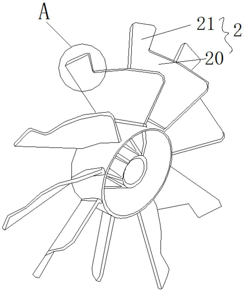
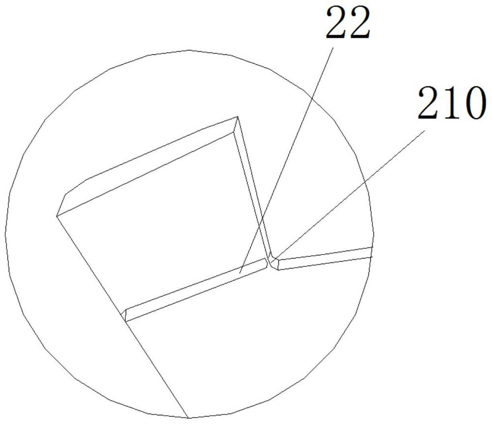
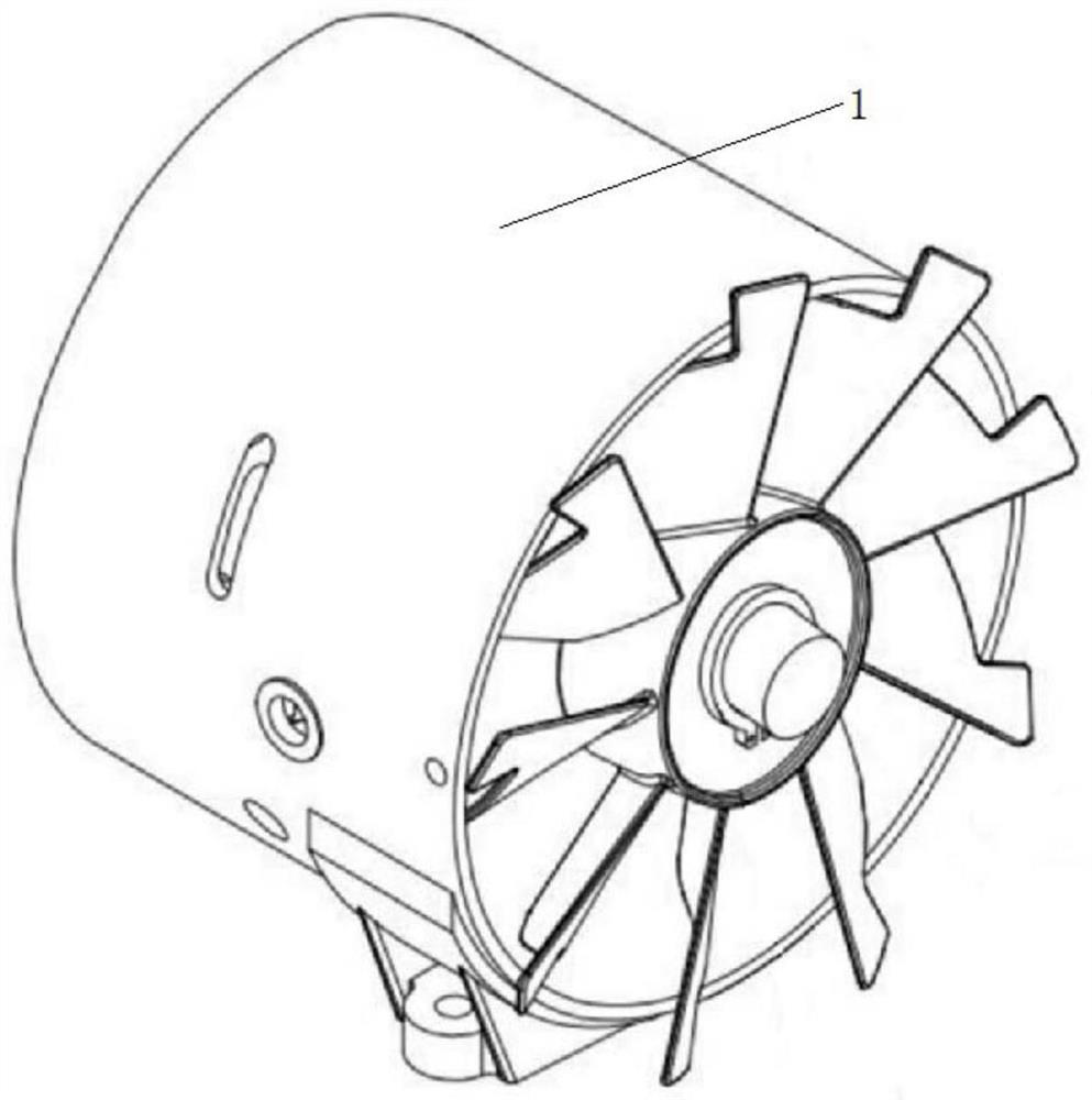
[0032] refer to Figure 1 to Figure 5 The embodiment of a heat dissipation mechanism for an air compressor and its control method according to the present invention will be further described.

[0033] For ease of description, if spatially relative terms such as "upper", "lower", "left", and "right" are used in the embodiments, they are used to describe the relative relationship between one element or feature shown in the figure and another element or feature Relationship. It will be understood that the spatial terms are intended to encompass different orientations of the device in use or operation in addition to the orientation depicted in the figures. For example, if the device in the figures is turned over, elements described as "below" other elements or features would then be oriented "above" the other elements or features. Thus, the exemplary term "lower" can encompass both an orientation of above and below. The device may be otherwise oriented (rotated 90 degrees or at...


PUM


Abstract

The invention discloses a heat dissipation mechanism for an air compressor and a control method thereof, and aims to provide a heat dissipation mechanism with bidirectional heat dissipation of the interior of a motor and a shell and an effect of controlling the state of an impeller. The heat dissipation mechanism is technically characterized in that a motor protection system for protecting the motor is arranged on a mounting cylinder; the motor protection system is set to include a controller for controlling on and off of the motor, an angle detection unit, a rotating speed detection unit anda motor current detection unit, the angle detection unit, the rotating speed detection unit and the motor current detection unit are electrically connected with the controller. With arrangment of thecontroller, angle detection, rotating speed detection and motor current detection are converted into detection of the motor state, the real-time and accurate monitoring effect on the draught fan is achieved, if the headwind state exists, the load current of the motor is increased, the rotating speed is reduced, normal operation of the draught fan can be maintained in a current increasing mode. Theheat dissipation mechanism is suitable for the technical field of air compressor equipment.

Description

technical field [0001] The invention relates to the technical field of air compressor equipment, more specifically, it relates to a heat dissipation mechanism for an air compressor and a control method thereof. Background technique [0002] Air compressors are air compressors, which are the basic products of industrial modernization. It is a device that converts the mechanical energy of the motor into gas pressure energy, and is a device that generates air pressure for compressed air. The air compressor is a miniature reciprocating piston compressor. Its working principle is: when the motor uniaxially drives the crankshaft of the compressor to rotate, through the transmission of the connecting rod, the piston with self-lubrication without adding any lubricant will reciprocate. The working volume formed by the inner wall of the cylinder, the cylinder head and the top surface of the piston will change periodically. With the increasing diversity of market demand, in order to ...

Claims


Application Information

Patent Timeline
IPC IPC(8): G01R31/34G01R19/00
CPCG01R31/343G01R19/0092
Inventor 王深广贺敬畏阮永幸
Owner 浙江永源机电制造有限公司
Why Eureka
Try Eureka