Anti-creeping testing device for numerical control machine tool research and development

A testing device and numerically controlled machine tool technology, which is applied to measuring devices, short-circuit testing, components of electrical measuring instruments, etc., can solve problems affecting the comprehensiveness and accuracy of testing, and achieve strong practicability and improve comprehensiveness and accuracy. Effect

Pending Publication Date: 2020-12-18
CHINA NORTH STANDARDIZATION CENT
View PDF8 Cites 0 Cited by
  • Summary
  • Abstract
  • Description
  • Claims
  • Application Information

AI Technical Summary

Problems solved by technology

Although the device can realize the leakage prevention test, it can only detect the top of the machine tool, and it is difficult to detect the side and bottom of the machine tool, which affects the comprehensiveness and accuracy of the test

Method used


Image

  • Anti-creeping testing device for numerical control machine tool research and development
  • Anti-creeping testing device for numerical control machine tool research and development
  • Anti-creeping testing device for numerical control machine tool research and development

Examples


Embodiment 1

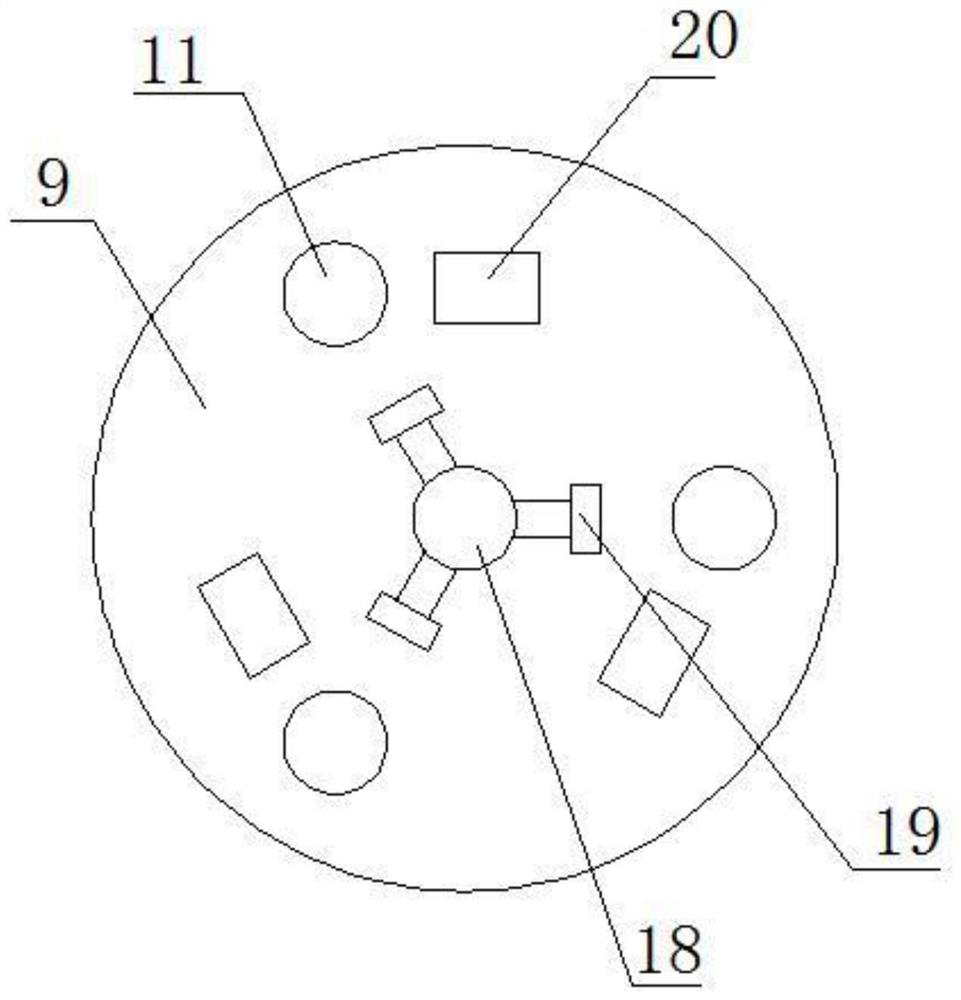
[0023] see Figure 1-5 , in an embodiment of the present invention, a leakage prevention test device for research and development of a numerically controlled machine tool, comprising a base 1, universal wheels 2 are provided at the four corners of the lower side of the base 1, and a first electric telescopic mechanism 3 is provided on the upper side of the base 1 , the upper end of the first electric telescopic mechanism 3 is provided with a first motor 4, the output end of the first motor 4 is provided with a second electric telescopic mechanism 5, and the right end of the second electric telescopic mechanism 5 is provided with a water tank 6 , the lower end of the water tank 6 is provided with a third electric telescopic mechanism 7, and the lower end of the third electric telescopic mechanism 7 is provided with a driving mechanism 8, and the driving mechanism 8 includes a first mounting seat 29, and the first mounting seat The inside of 29 is provided with mounting groove 3...

Embodiment 2

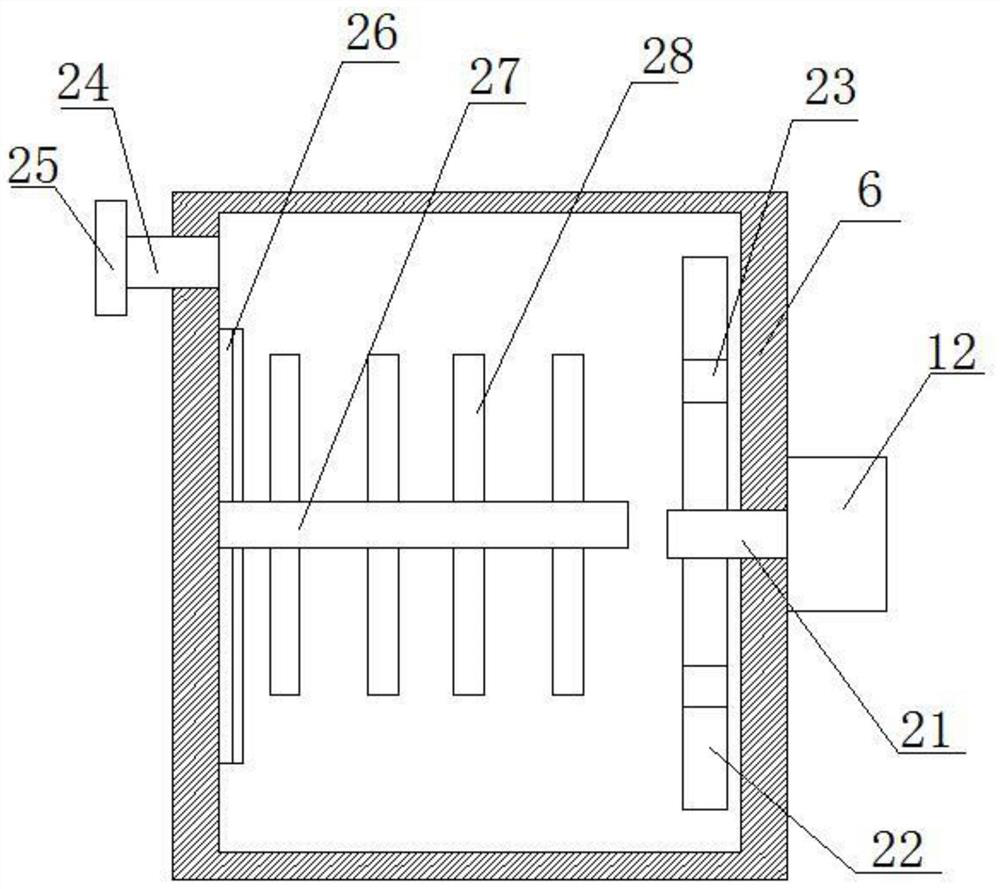
[0028]On the basis of Embodiment 1, a water supply pipe 24 is provided on the left side of the water tank 6, a sealing cover 25 is provided on the water supply pipe 24, a T-shaped slide rail 26 is provided on the left side of the water tank 6, and the inside of the water tank 6 A floating board 27 is provided, and the floating board 27 is connected with the T-shaped slide rail 26 through a T-shaped chute 36. The upper and lower sides of the floating board 27 are symmetrically provided with wave-blocking boards 28, and the floating board 27 is provided with several passageways. Water hole 37. The setting of this structure can reduce the shaking of water when the device is moving, reduce the impact force on the water tank 6, prolong the service life of the water tank 6, and ensure the stability of the device.


PUM


Abstract

The invention relates to the field of numerical control machine tool research and development, in particular to an anti-creeping testing device for numerical control machine tool research and development. A water tank is arranged at the right end of a second electric telescopic mechanism, a third electric telescopic mechanism is arranged at the lower end of the water tank, and a driving mechanismis arranged at the lower end of the third electric telescopic mechanism. The driving mechanism comprises a first mounting base, a mounting groove is formed in the first mounting base, a second motor is arranged on the outer side of the first mounting base, a second mounting base is connected to the interior of the mounting groove through a first rotating shaft, the output end of the second motor is connected with the first rotating shaft, and a third motor is arranged in the second mounting base; and a second rotating shaft is arranged at the output end of the third motor, a rotating seat is arranged at the outer end of the second rotating shaft, and an electric leakage test main body is arranged in the right side of the rotating seat. The structure can achieve the omnibearing anti-electric leakage test of the machine tool, the comprehensiveness and accuracy of the test are improved, and the practicability is high.

Description

technical field [0001] The invention relates to the field of research and development of numerical control machine tools, in particular to an anti-leakage test device for research and development of numerical control machine tools. Background technique [0002] CNC machine tool is the abbreviation of digital control machine tool. It is an automatic machine tool equipped with a program control system. It can make the machine tool move and process parts according to the programmed program. technology. The basic composition of CNC machine tools includes processing program carrier, CNC device, servo drive device, machine tool body and other auxiliary devices. A CNC machine tool is loaded with many components and requires a lot of power when it is working. Before it is put into use, it needs to be adjusted. These CNC machines are tested for leak resistance. The anti-leakage test for the research and development of CNC machine tools on the market usually uses electric pens or mu...

Claims


Application Information

Patent Timeline
IPC IPC(8): G01R31/52G01R1/02
CPCG01R31/52G01R1/02
Inventor 邱继伟罗海胜
Owner CHINA NORTH STANDARDIZATION CENT
Why Eureka
Try Eureka