Eureka AIR delivers breakthrough ideas for toughest innovation challenges, trusted by R&D personnel around the world.

Optical fiber array and manufacturing method thereof

A technology of optical fiber array and manufacturing method, which is applied in the field of optical fiber, can solve problems such as product problems such as failure to work normally and reliably, temperature rise of optical modules, and capping of positioning components, so as to facilitate large-scale popularization and application, improve reliability, The effect of ensuring stability

Inactive Publication Date: 2020-12-18
WUHAN YILUT TECH CO LTD
View PDF12 Cites 0 Cited by
  • Summary
  • Abstract
  • Description
  • Claims
  • Application Information

AI Technical Summary

Problems solved by technology

The traditional optical fiber array positioning components are made of glass and bonded with UV-cured glue, which has the following problems in the production and practical process: poor reliability
Since the photoelectric module usually generates heat during operation, the temperature of the optical module rises. After a temperature cycle or a high-temperature and high-humidity environment, the glue may crack or degumming the positioning components, resulting in problems with the product that cannot be used normally and reliably. Work

Method used


Image

  • Optical fiber array and manufacturing method thereof
  • Optical fiber array and manufacturing method thereof

Examples


Embodiment Construction

[0035] The principles and features of the present invention are described below in conjunction with the accompanying drawings, and the examples given are only used to explain the present invention, and are not intended to limit the scope of the present invention.

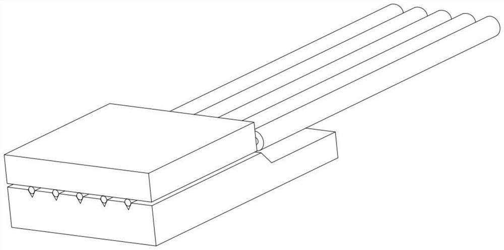
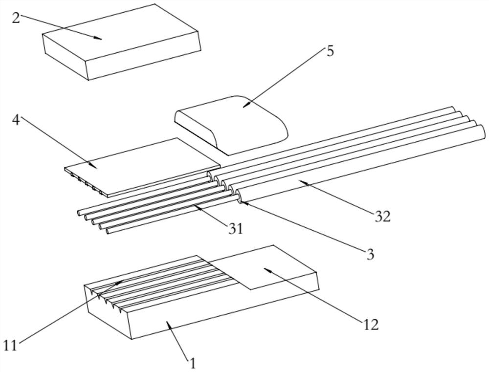
[0036] Such as figure 1 with figure 2 As shown, an optical fiber array includes a base 1, a cover plate 2 matching the base 1, a group of optical fibers 3, a solder layer 4 matching the base 1 and a curing glue 5, the base 1 One end is higher than the other end, and a step 12 is formed on its upper surface, a plurality of V-shaped grooves 11 are provided on the upper surface of the higher end of the base 1, and one end of the optical fiber 3 peels off the coating layer 32 and exposes the cladding 31 , and one end of the optical fiber 3 exposed to the cladding is arranged one by one in the V-shaped groove 11, the cover plate 2 is covered on the base 1, and the solder layer 4 is located on the base 1 and the cover ...


PUM

PropertyMeasurementUnit
Thicknessaaaaaaaaaa
Thicknessaaaaaaaaaa

Abstract

The invention relates to an optical fiber array and a manufacturing method thereof. The optical fiber array comprises a base, a cover plate, a set of optical fibers, a solder layer and curing glue, one end of the base is higher than the other end to form a step, multiple V-shaped grooves are formed in the upper surface of the higher end of the base, and one end of each optical fiber is stripped from a coating layer and a cladding is exposed; the ends, exposed out of the cladding, of the optical fibers are arranged in the V-shaped grooves in a one-to-one correspondence mode, the cover plate covers the base, the solder layer is located between the upper surface of the base and the cover plate, and the base and the cover plate are fixed so that one ends of the optical fibers can be fixed in the V-shaped grooves, and the other ends of the optical fibers can be located at the lower end of the base. The curing adhesive fixes the other ends of the optical fibers at the lower end of the base.According to the optical fiber array, the stability of the optical fibers is guaranteed, the reliability of the whole optical fiber array is improved, the situation that the stability of the optical fibers is affected due to looseness or dislocation of optical fiber fixation caused by temperature rise during work is avoided, and the optical fiber array is simple in structure, low in manufacturingcost and convenient to apply and popularize on a large scale.

Description

technical field [0001] The invention relates to the field of optical fiber technology, in particular to an optical fiber array and a manufacturing method thereof. Background technique [0002] With the rapid development of technologies such as big data and 5G, optical fiber arrays have been widely used in optoelectronic modules, wavelength division multiplexing systems, wavelength selective switches and other products. The traditional optical fiber array positioning components are made of glass and bonded with UV-cured glue, which has the following problems in the production and practical process: poor reliability. Since the photoelectric module usually generates heat during operation, the temperature of the optical module rises. After a temperature cycle or a high-temperature and high-humidity environment, the glue may crack or degumming the positioning components, resulting in problems with the product that cannot be used normally and reliably. Work. Contents of the inv...

Claims


Application Information

Patent Timeline
IPC IPC(8): G02B6/36
CPCG02B6/3636
Inventor 胡诚余创黄望隆
Owner WUHAN YILUT TECH CO LTD
Why Eureka
Eureka Blog
Learn More