
Temperature control assembly and battery pack

A technology for temperature control components and battery packs, applied in secondary batteries, battery pack components, circuits, etc., can solve the problems of reducing the expansion force, reducing the service life, reducing the service life of the battery, etc., so as to reduce the expansion force and improve the Service life, the effect of prolonging the service life

Pending Publication Date: 2020-12-18
CONTEMPORARY AMPEREX TECH CO
View PDF0 Cites 4 Cited by
  • Summary
  • Abstract
  • Description
  • Claims
  • Application Information

AI Technical Summary

Problems solved by technology

Among them, an appropriate expansion force will be beneficial to the battery's own reaction, but an excessive expansion force will cause the battery to be overstressed and cause lithium precipitation, and even cause irreversible capacity loss, which greatly reduces the battery life.
[0005] In order to alleviate the expansion force, there are mainly the following forms: (1) The batteries are directly attached to each other and the external structure is strengthened to directly resist the expansion force. The disadvantage of this method is: when the battery capacity and the battery string When the number gradually increases, the expansion force after the batteries are grouped will become larger and larger, thereby reducing the service life of the battery; The disadvantage of this method is that: the large surface of the battery is close to the cushion pad, and only the side and bottom of the battery can be used to dissipate heat, thereby reducing the heat dissipation efficiency; (3) the battery is separated from the battery, and the middle space The gap is opened to allow the battery to expand freely. The disadvantage of this method is that the battery expands freely at the beginning, and it is easy to react insufficiently without pressure, which reduces the service life. When it is too large, it will affect the group volume

Method used

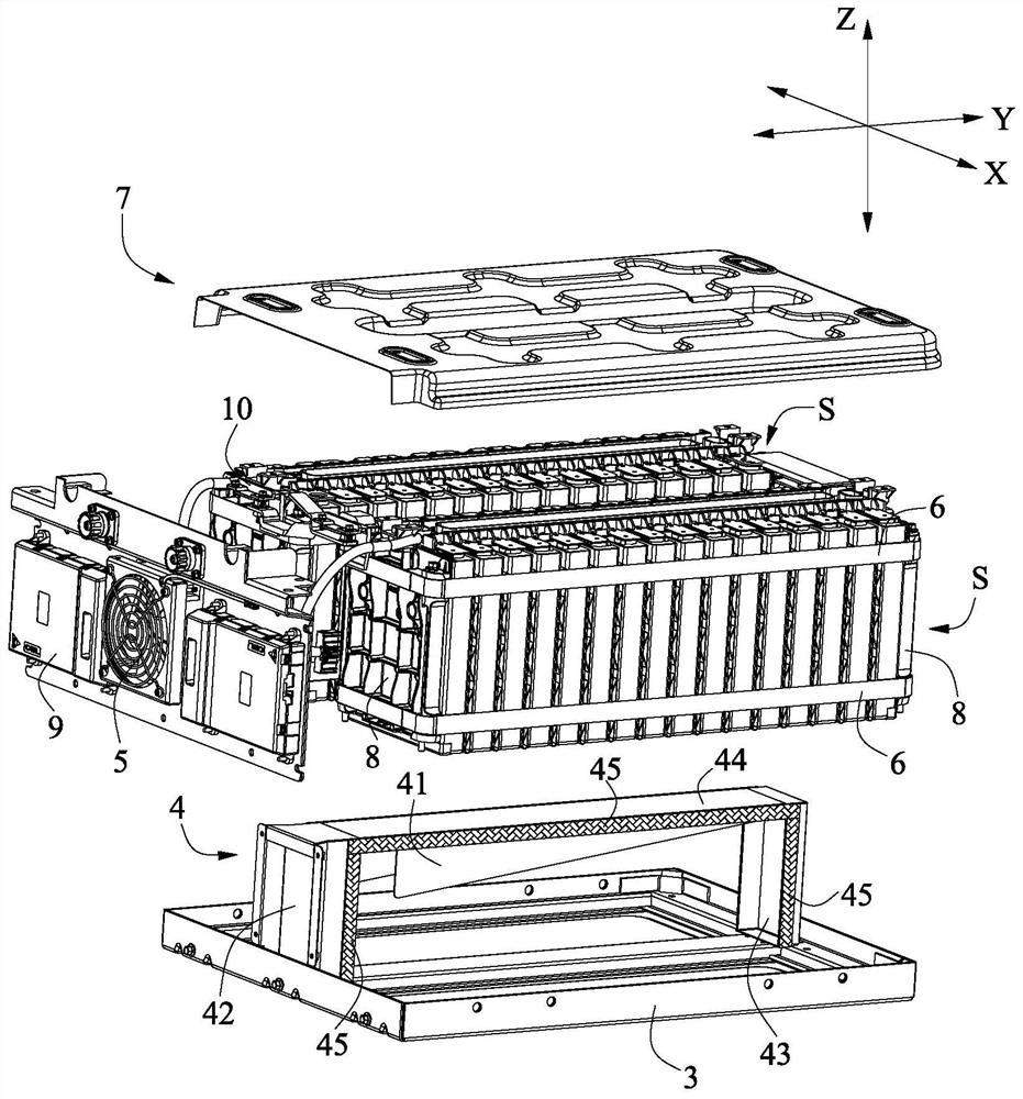
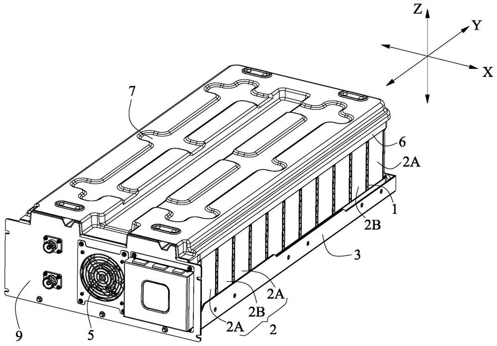
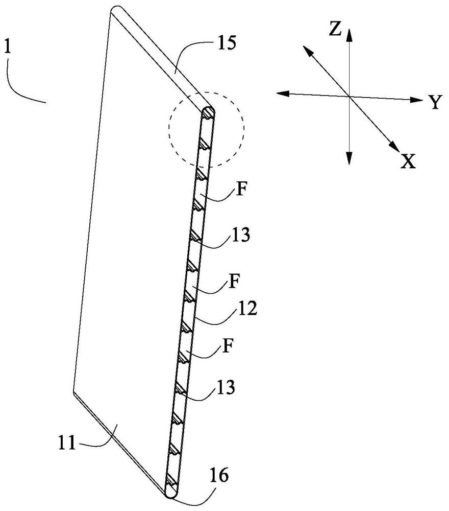

Image

  • Temperature control assembly and battery pack
  • Temperature control assembly and battery pack
  • Temperature control assembly and battery pack

Examples


Embodiment Construction

[0044] In order to make the purpose, technical solution and advantages of the present application clearer, the present application will be further described in detail below in conjunction with the accompanying drawings and embodiments. It should be understood that the specific embodiments described here are only used to explain the present application, and are not intended to limit the present application.

[0045] In the description of this application, unless otherwise clearly specified and limited, the terms "first" and "second" are only used for the purpose of description, and cannot be understood as indicating or implying relative importance; the term "plurality" is Refers to two or more (including two); unless otherwise specified or explained, the term "connection" should be understood in a broad sense, for example, "connection" can be a fixed connection, a detachable connection, or an integral connection, or Electrical connection, or signal connection; "connection" can ...


PUM


Abstract

The invention provides a temperature control assembly and a battery pack. The temperature control assembly comprises a first side plate, a second side plate and a first buffer plate. The first bufferplate is arranged between the second side plate and the first side plate so as to divide a cavity into a plurality of channels, and at least a part of the first buffer plate obliquely extends from thefirst side plate to the second side plate. When external air flows through a channel of the temperature control assembly, heat dissipation treatment of the battery can be realized. In a use process of the battery pack, an expansion force of two adjacent batteries extrudes the first side plate and the second side plate respectively, and at least a part of the first buffer plate obliquely extends so that the expansion force transmitted to the first buffer plate is greatly reduced, and the service life of the temperature control assembly is prolonged. Moreover, at least a part of the first buffer plate obliquely extending is easier to bend and deform under the action of expansion force so that the temperature control assembly can timely absorb the expansion force of the battery, and the service life of the battery is prolonged.

Description

technical field [0001] The invention relates to the technical field of batteries, in particular to a temperature control component and a battery pack. Background technique [0002] A battery pack typically includes multiple batteries grouped together. In group technology, in addition to ensuring the strength and performance of the structure itself, it is also necessary to consider the impact of the structure on battery life, in which temperature and expansion force have a great impact on battery life, so thermal management and expansion force design must be considered in design. [0003] In terms of thermal management design: At present, there are mainly two ways of water cooling and air cooling. Among them, due to the high cost of the water cooling method, the battery pack generally adopts the air cooling method for heat dissipation. [0004] In terms of expansion force design: During the charging and discharging process of the battery pack, the battery will gradually exp...

Claims


Application Information

Patent Timeline
Patent Type & Authority Applications(China)
IPC IPC(8): H01M2/10H01M10/613H01M10/647H01M10/6555H01M10/6557H01M10/6563
CPCH01M10/613H01M10/647H01M10/6555H01M10/6557H01M10/6563Y02E60/10
Inventor 宿永强黄银成吴布维邓庆元周灵刚赵丰刚马俊
Owner CONTEMPORARY AMPEREX TECH CO
Learn More