Limiting and clamping device for machining center

A technology of machining center and clamping device, which is applied in the direction of clamping device, positioning device, metal processing, etc., can solve the problem of difficulty in meeting the continuous production requirements of machining centers, poor clamping efficiency and positioning accuracy, affecting feeding efficiency and positioning accuracy, etc. problems, to meet the needs of compact continuous production, improve positioning accuracy, and reduce life loss

Active Publication Date: 2020-12-22
苏州艾米欧精密机械股份有限公司
View PDF8 Cites 3 Cited by
  • Summary
  • Abstract
  • Description
  • Claims
  • Application Information

AI Technical Summary

Problems solved by technology

The limit clamping of CNC machining center equipment in the prior art generally adopts clamping tooling, especially when the workpiece structure needs to be fixed at multiple points, resulting in poor clamping efficiency and positioning accuracy. The surface of the bar workpiece is reliably clamped. At the same time, when the vertical lifting limit structure is adopted on the conveyor of the machining center, the impact of the lifting impact on the conveyor will easily reduce the life of the conveyor. When the overall length of multiple workpieces is long, especially continuous When processing and loading from the top, it is necessary to repeatedly shift the limit structure to make way for the loading, and the repeated limit positioning will affect the feeding efficiency and the positioning accuracy of batch processing, and it is difficult to meet the compact continuous production requirements of the machining center

Method used


Image

  • Limiting and clamping device for machining center
  • Limiting and clamping device for machining center
  • Limiting and clamping device for machining center

Examples


Embodiment Construction

[0027] The specific embodiments of the present invention will be further described below in conjunction with the accompanying drawings.

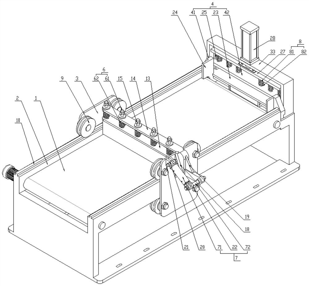
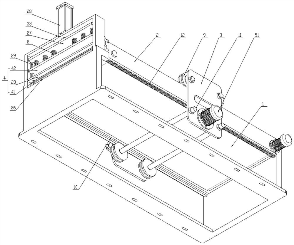
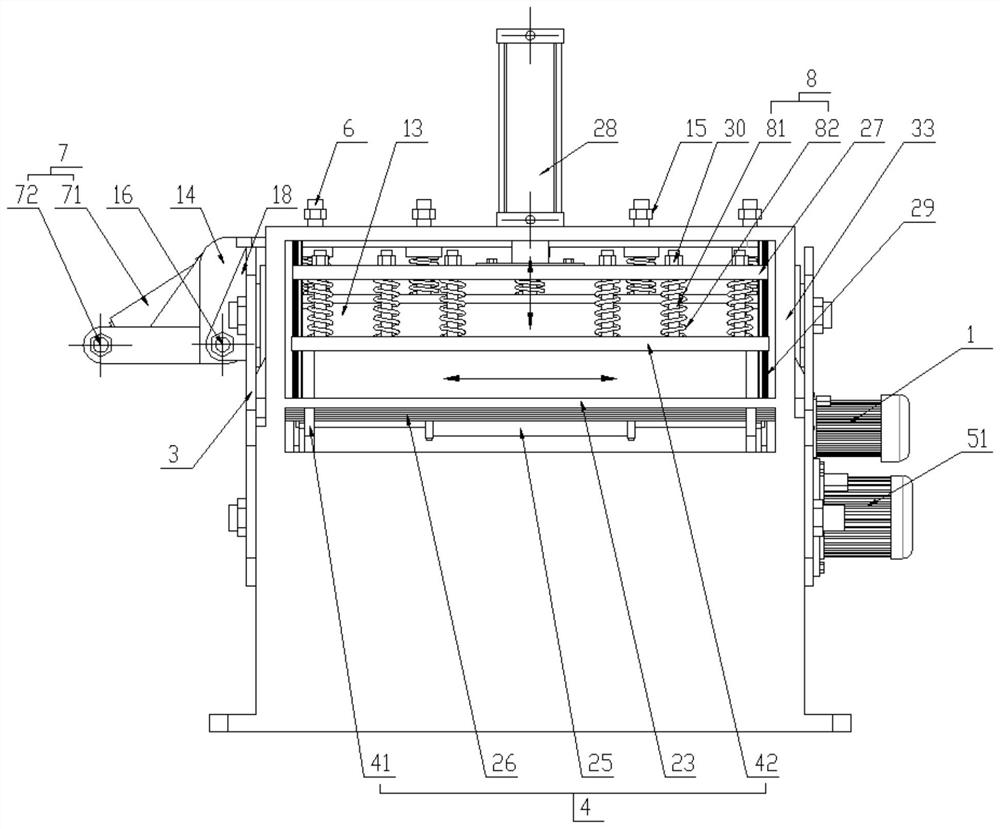
[0028] A limit clamping device for a machining center, comprising a frame 2 outside the conveyor 1 of the machining center, wherein the frame 2 is provided with at least one limit frame 3 and a clamping mechanism 4, the limit frame 3, a traveling drive mechanism 5 is provided on one side, and the traveling driving mechanism 5 is used to drive the limit frame 3 to reciprocate along the parallel direction of the conveyor 1;

[0029] The spacer 3 includes a first shelf 31 and a second shelf 32 positioned on both sides of the frame 2, and at least one roller 9 is arranged inside the first shelf 31 and the second shelf 32. The frame 2 is provided with a raceway 10 parallel to the conveyor 1 and located at the bottom of the rollers 9 or between the corresponding rollers 9 and rolling with the rollers 9. The rollers 9 at the bottom of the frame 2 a...


PUM


Abstract

The invention relates to a limiting and clamping device for a machining center. The device comprises a rack outside a machining center conveyor, the rack is provided with at least one limiting frame and a clamping mechanism, a walking driving mechanism used for driving the limiting frame to reciprocate in the parallel direction of the conveyor is arranged at one side of the limiting frame, a driving plate is arranged at the top of a limiting plate of the limiting frame, a deflection shaft and a deflection mechanism are arranged between the driving plate and the other side of the limiting frame, the deflection mechanism is used for driving the driving plate to deflect around the deflection shaft in a reciprocating manner, and the clamping mechanism comprises two first clamping plates movingoppositely in the vertical conveying direction of the conveyor and a second clamping plate moving relative to a fixing table in a lifting manner. The walking limiting frame drives the driving plate to deflect in a reciprocating manner through the deflection mechanism, side opening and closing of the limiting plate at the top of the conveyor can be achieved, top feeding is facilitated, repeated positioning is avoided, workpiece clamping is achieved through multi-face limiting clamping in the side direction and the vertical direction of the clamping mechanism, the positioning precision, the clamping efficiency and the reliability can be improved, and the compact continuous production requirement of the machining center is met.

Description

technical field [0001] The invention relates to a position-limiting clamping device for a machining center, which belongs to the technical field of numerical control machining center equipment. Background technique [0002] The high-efficiency automatic CNC machining center, which is composed of mechanical equipment and CNC system, is suitable for processing complex parts. It has the characteristics of high processing precision and batch processing efficiency. It is widely used in milling, boring, drilling, sawing and other processing procedures. Among them, the limit clamping device is involved on the conveyor of the machine tool, which is used for limit clamping and positioning of one or more workpieces, so as to control the processing position and prevent the displacement and vibration of the workpiece during the machining process of the machining center, which will affect the machining accuracy. The limit clamping of CNC machining center equipment in the prior art genera...

Claims


Application Information

Patent Timeline
Patent Type & Authority Applications(China)
IPC IPC(8): B23Q3/00B23Q7/00
CPCB23Q3/00B23Q7/00B23Q2703/04
Inventor 赵海军
Owner 苏州艾米欧精密机械股份有限公司
Why Eureka
Try Eureka