Billiard cue processing device
A processing device and technology for billiard cues, which are used in wood processing appliances, manufacturing tools, special forming/shaping machines, etc., can solve the problems of discarded cues, uneven grinding, waste of resources, etc., and achieve the effect of avoiding accumulation
- Summary
- Abstract
- Description
- Claims
- Application Information
AI Technical Summary
Problems solved by technology
Method used
Image

Examples
specific Embodiment approach 1
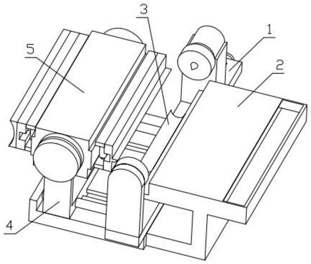
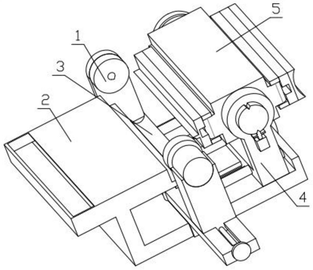
[0032] Combine below Figure 1-13Description of this embodiment, a billiard cue processing device, including a log clamping mechanism 1, a feed box 2, a feeding mechanism 3, a rotating mechanism 4 and a processing mechanism 5, the log clamping mechanism 1 is fixedly installed on the rotating mechanism 4, the feeding box 2 is fixedly installed on the rotating mechanism 4, the feeding mechanism 3 is fixedly installed on the log clamping mechanism 1, and the processing mechanism 5 is fixedly installed on the rotating mechanism 4.
specific Embodiment approach 2
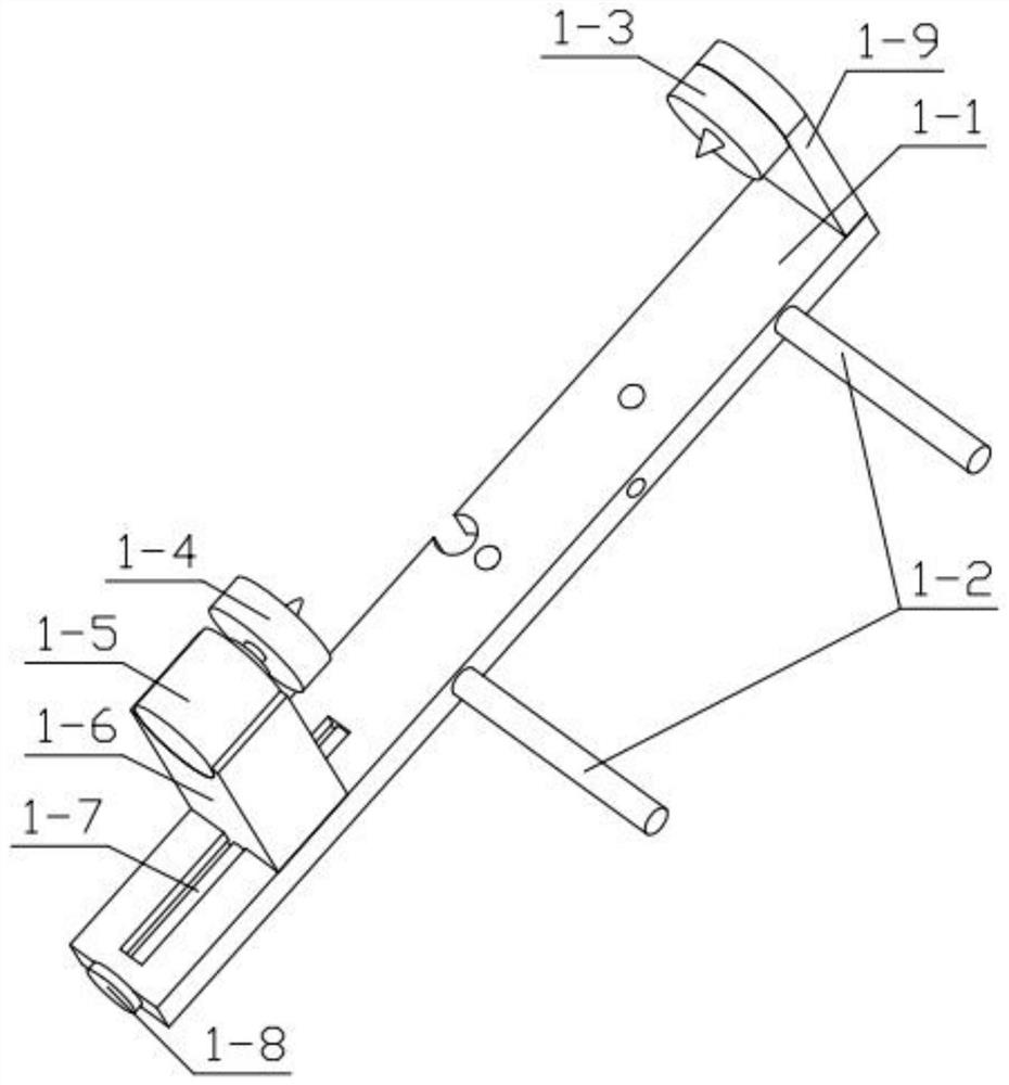
[0034] Combine below Figure 1-13 Describe this embodiment, this embodiment will further explain the first embodiment, the log clamping mechanism 1 includes a strip bottom plate 1-1, a limit post 1-2, a positioning member 1-3, and a rotating positioning member 1-4 , rotating motor 1-5, sliding base 1-6, threaded rod 1-7, rotating disk 1-8, support plate 1-9, support plate 1-9 is fixedly installed on one end of strip base plate 1-1, and positioning piece 1-3 is rotatably installed in the groove provided on the support plate 1-9, the limit column 1-2 is fixedly installed on the strip bottom plate 1-1, and the sliding base 1-6 is slidably installed on the strip bottom plate 1-1. In the groove provided at one end, one end of the threaded rod 1-7 is rotatably installed in the groove provided on the strip bottom plate 1-1, and the other end of the threaded rod 1-7 passes through the strip bottom plate 1-1 and is fixedly installed with a rotating disk 1-8, the sliding base 1-6 is th...
specific Embodiment approach 3
[0036] Combine below Figure 1-13 Describe this embodiment, this embodiment will further explain the second embodiment, the feeding mechanism 3 includes an arc-shaped groove plate 3-1, a U-shaped fixing frame 3-2, a sprocket wheel 3-3, and a threaded stub 3 -4, lifting motor 3-5, lifting gear 3-6, baffle plate 3-7, chain 3-8, U-shaped fixed mount 3-2 is fixedly installed on the strip base plate 1-1, sprocket wheel 3- 3 Rotate and install in the groove provided on the U-shaped fixed frame 3-2, the sprocket 3-3 is threaded with the threaded short post 3-4, and the threaded short post 3-4 is fixedly installed on the arc groove plate 3-1 , baffle plate 3-7 is fixedly installed on arc groove plate 3-1, sprocket wheel 3-3 is meshed with chain 3-8, sprocket wheel 3-3 is meshed with lifting gear 3-6, and lifting gear 3 -6 is fixedly installed on the output end of the lifting motor 3-5, and the lifting motor 3-5 is fixedly installed in the groove provided on the strip bottom plate 1-1...
PUM
 Abstract
Description
Claims
Application Information
 - R&D
- Intellectual Property
- Life Sciences
- Materials
- Tech Scout
- Unparalleled Data Quality
- Higher Quality Content
- 60% Fewer Hallucinations
Browse by: Latest US Patents, China's latest patents, Technical Efficacy Thesaurus, Application Domain, Technology Topic, Popular Technical Reports.
© 2025 PatSnap. All rights reserved.Legal|Privacy policy|Modern Slavery Act Transparency Statement|Sitemap|About US| Contact US: help@patsnap.com