EPS foam forming equipment

A technology of foam molding and equipment, which is applied in the field of EPS foam preparation, can solve the problems of uneven particle size, uneven specific gravity and large influence of pre-expanded beads, and achieve a small product density gradient, particle size and specific gravity. The effect of uniformity and uniform specific gravity

Active Publication Date: 2020-12-22
安徽祥欣新材料科技有限公司
View PDF10 Cites 0 Cited by
  • Summary
  • Abstract
  • Description
  • Claims
  • Application Information

AI Technical Summary

Problems solved by technology

[0002] The process of EPS foam molding includes pre-expansion, aging and molding. The pre-expansion is to heat the EPS bead product to make it expand to a certain extent. In the industry, a continuous steam pre-expansion machine is often used to feed the pellets. The container is continuously fed into the cylinder, and the beads are heated and expanded. Under the action of stirring, due to the different densities, the heavier ones are on the bottom and the lighter ones are on the top. The feed port is pushed into the air duct by centrifugal force and enters the blower. Although the process of steam pre-foaming is simple, it still has the following disadvantages: when the steam pre-foaming time is the same, some beads are not pre-foamed completely, The resulting pre-expanded beads have uneven particle size and specific gravity, resulting in a large density gradient in the product, and pre-expansion materials with different densities have a greater impact on the subsequent foam molding process, which can easily lead to The density of the finished foam is uneven, which affects the strength or shape; the collision between the EPS beads in the pre-expansion process produces more debris, resulting in uneven product density, so further improvement of the existing equipment is required

Method used


Image

  • EPS foam forming equipment
  • EPS foam forming equipment
  • EPS foam forming equipment

Examples


Embodiment

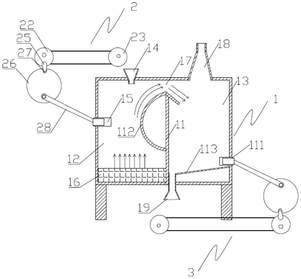
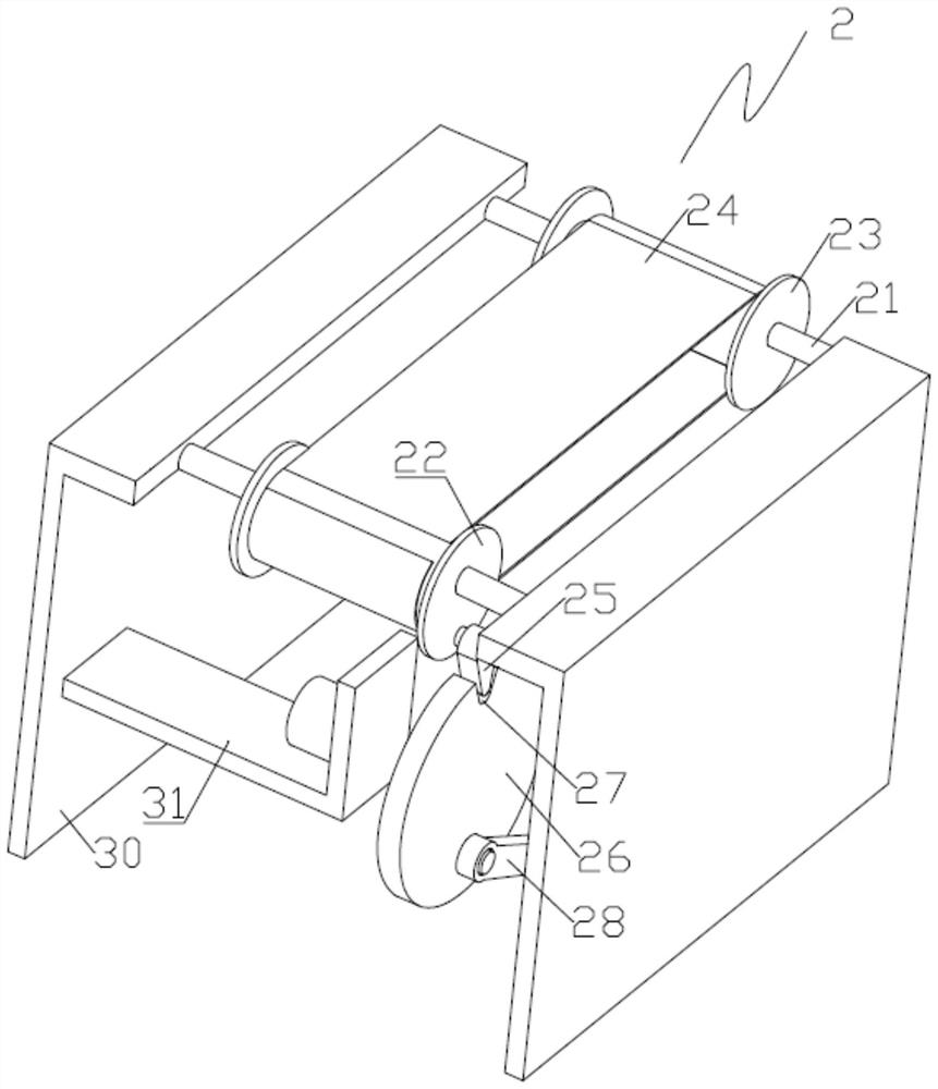
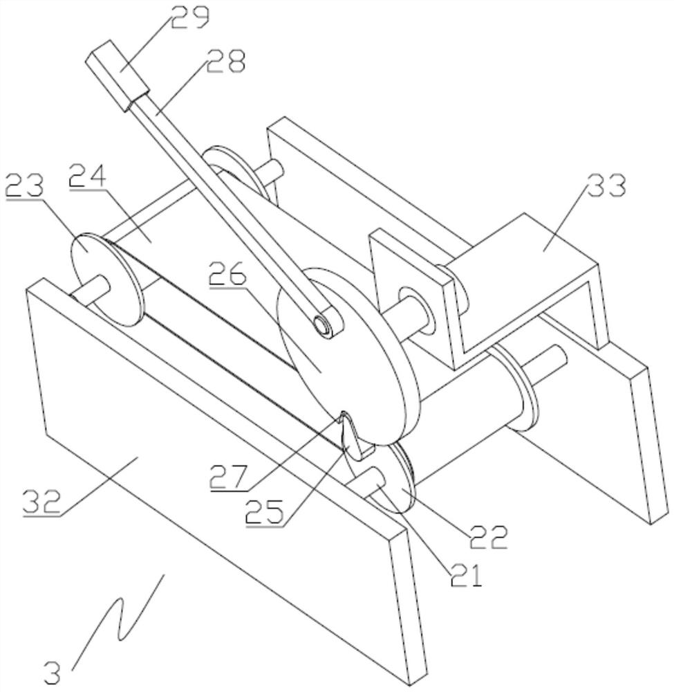
[0017] like Figure 1 to Figure 3 As shown, an EPS foam molding equipment includes a foaming box 1, a driving device 1 for feeding and blowing air to the foaming box 1, and a driving device 2 for discharging and blowing air to the foaming box 1 3 , the foaming box 1 is provided with a partition 11 and is divided into a foaming chamber 12 and a sorting chamber 13 by the partition 11, the top of the foaming chamber 12 is provided with a feed hopper 14 and its outside Air inlet pipe one 15 is provided, the bottom of the foaming chamber 12 is provided with a steam generator 16 and steam is injected into the foaming chamber 12 through the steam generator 16, between the top of the foaming chamber 12 and the dividing plate 11 Form inlet 17, the top of described sorting chamber 13 is equipped with collecting cover 18, and described collecting cover 18 upper end is communicated with negative pressure fan, and the bottom of described sorting chamber 13 is provided with discharge port 1...


PUM


Abstract

The invention discloses EPS (expandable polystyrene) foam forming equipment, and relates to the field of EPS foam preparation. The EPS foam forming equipment comprises a foaming box body, a first driving device and a second driving device, wherein the first driving device is used for feeding and supplying air to the foaming box body, and the second driving device is used for discharging and supplying air to the foaming box body. According to the EPS foam forming equipment, EPS beads are pre-foamed through a steam generator; through the cooperative use of the first driving device, a feeding hopper and a first air admission pipe, pre-foamed large-size EPS beads are blown into a sorting chamber, and unfoamed EPS beads continue to stay in a foaming chamber to be foamed, so that feeding and airsupply do not interfere with each other, the situation that the newly-fed unfoamed EPS beads are blown into a guide-in opening by mistake is avoided, finally, the particle size and specific gravity of the EPS beads capable of being blown into the guide-in opening are uniform, and the product density gradient is small; and through the cooperative use of the second driving device, a discharging opening and a second air admission pipe and the effect of a negative pressure draught fan, chippings formed by collision of the pre-foamed EPS beads are removed, and finally the pre-foamed EPS beads withuniform specific gravity and small density gradient are collected.

Description

technical field [0001] The invention relates to the field of EPS foam preparation, in particular to EPS foam molding equipment. Background technique [0002] The process of EPS foam molding includes pre-expansion, aging and molding. The pre-expansion is to heat the EPS bead product to make it expand to a certain extent. In the industry, a continuous steam pre-expansion machine is often used to feed the pellets. The container is continuously fed into the cylinder, and the beads are heated and expanded. Under the action of stirring, due to the different densities, the heavier ones are on the bottom and the lighter ones are on the top. The feed port is pushed into the air duct by centrifugal force and enters the blower. Although the process of steam pre-foaming is simple, it still has the following disadvantages: when the steam pre-foaming time is the same, some beads are not pre-foamed completely, The resulting pre-expanded beads have uneven particle size and specific gravity...

Claims


Application Information

Patent Timeline
Patent Type & Authority Applications(China)
IPC IPC(8): B29C44/34
CPCB29C44/34B29C44/3461B29C44/35
Inventor 张强赵高林
Owner 安徽祥欣新材料科技有限公司
Why Eureka
Try Eureka