
Multi-angle rotating spherical hinge support system for building steel grid structure

A grid structure, spherical hinge bearing technology, applied in building structure, construction and other directions, can solve problems such as large concentrated stress, inconvenient installation, building bearing damage, etc., to eliminate concentrated stress, ensure stability, increase The effect of stability

Active Publication Date: 2020-12-22
CHINA CONSTR EIGHTH ENG DIV
View PDF6 Cites 3 Cited by
  • Summary
  • Abstract
  • Description
  • Claims
  • Application Information

AI Technical Summary

Problems solved by technology

[0002] With the rapid development of society and the advancement of human civilization, people have higher and higher requirements for beautiful and lightweight buildings. Therefore, more and more buildings use overall hoisting, lightweight systems, and transparent and bright architectural appearance to interpret architectural aesthetics. To meet people's needs, the steel grid frame is the basic structure of many prefabricated buildings. Since most of the traditional grid systems are rigidly connected, no matter the safety of the connection method or the bulkiness of the structural system, they cannot satisfy people's expectations for the building space structure. The demand for safety and architectural aesthetics, and it is not adjustable, which brings a lot of inconvenience to the installation process. Due to the effect of wind loads in all directions, steel grid buildings do not have the reserved adjustable space. A large fixed-end bending moment will be formed at the seat, resulting in a large concentrated stress and causing damage to the building support.

Method used


Image

  • Multi-angle rotating spherical hinge support system for building steel grid structure
  • Multi-angle rotating spherical hinge support system for building steel grid structure

Examples


Embodiment Construction

[0017] The following will clearly and completely describe the technical solutions in the embodiments of the present invention with reference to the accompanying drawings in the embodiments of the present invention. Obviously, the described embodiments are only some, not all, embodiments of the present invention. Based on the embodiments of the present invention, all other embodiments obtained by persons of ordinary skill in the art without making creative efforts belong to the protection scope of the present invention.

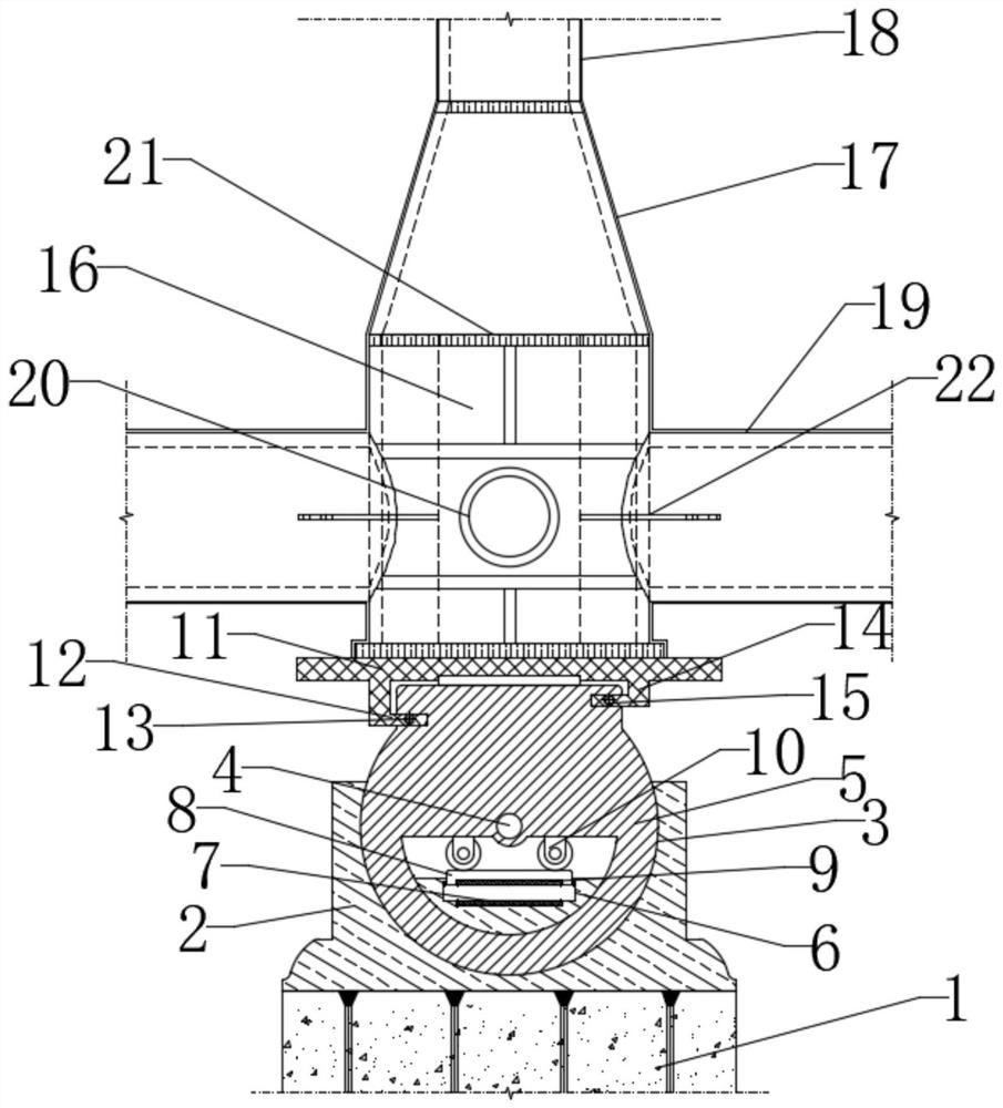
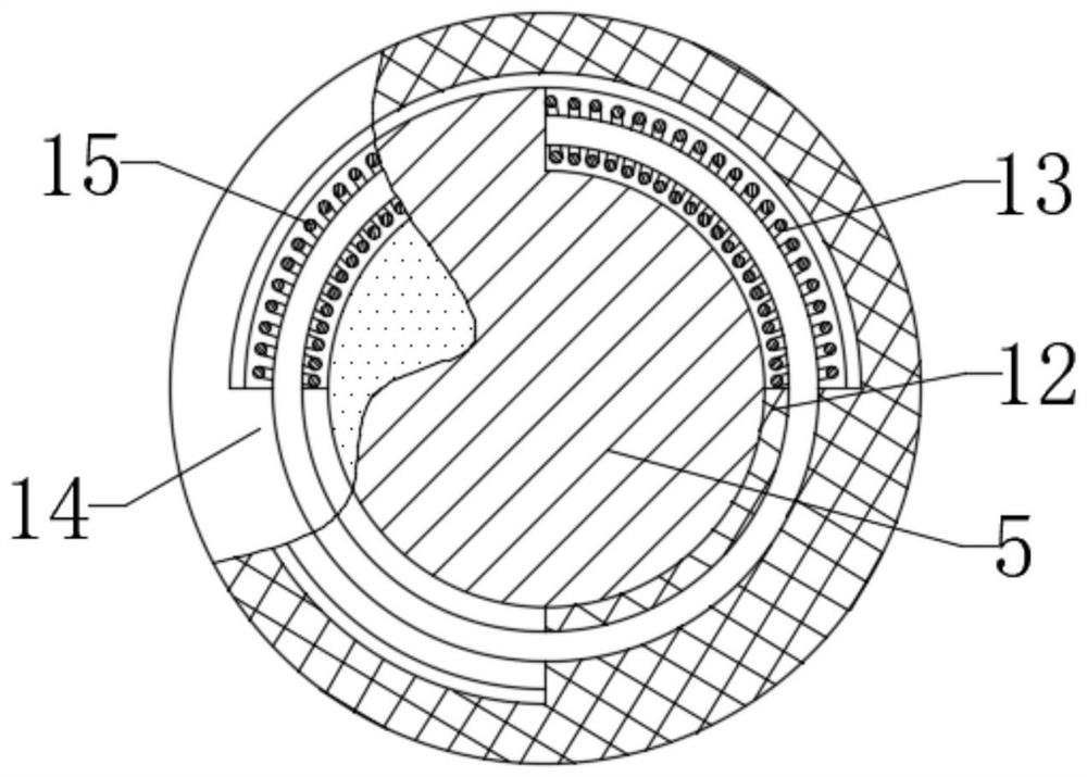
[0018] see Figure 1 to Figure 2 , the present invention provides a technical solution: a multi-angle rotating spherical hinge support system for a building steel grid structure, including an embedded part 1, a support 2 is fixedly installed on the embedded part 1, and the support 2 is set There is a rotating groove 3, a central shaft 4 is fixedly installed in the rotating groove 3, and a movable seat 5 is movably connected in the rotating groove 3, a sliding ...


PUM


Abstract

The invention relates to the technical field of building construction, in particular to a multi-angle rotating spherical hinge support system for a building steel grid structure. The multi-angle rotating spherical hinge support system for the building steel grid structure comprises an embedded part, a support is fixedly mounted on the embedded part, a rotating groove is formed in the support, a central shaft is fixedly mounted in the rotating groove, a movable seat is movably connected to the interior of the rotating groove; a sliding groove is formed in the support, a first magnetic block isfixedly mounted in the sliding groove, a limiting plate is mounted in the sliding groove in a sliding mode, a second magnetic block is fixedly mounted on the limiting plate, and a guide wheel is fixedly mounted on the movable seat. by using the embedded part and the support as structural bases, and mounting the adjustable movable seat and an adjustable rotating disc on the embedded part and the support to serve as connecting components, excessive bending moment and torque can be prevented from being generated in the structure, concentrated stress is eliminated, and the safety of the structureis protected; and meanwhile, as a magnetic reset structure is arranged in the movable seat and a spring return structure is mounted on the rotating disc, the structural stability can be guaranteed.

Description

technical field [0001] The invention relates to the technical field of building construction, in particular to a multi-angle rotating spherical hinge support system for building steel grid structures. Background technique [0002] With the rapid development of society and the advancement of human civilization, people have higher and higher requirements for beautiful and lightweight buildings. Therefore, more and more buildings use overall hoisting, lightweight systems, and transparent and bright architectural appearance to interpret architectural aesthetics. To meet people's needs, the steel grid frame is the basic structure of many prefabricated buildings. Since most of the traditional grid systems are rigidly connected, no matter the safety of the connection method or the bulkiness of the structural system, they cannot satisfy people's expectations for the building space structure. The demand for safety and architectural aesthetics, and it is not adjustable, which brings a...

Claims


Application Information

Patent Timeline
IPC IPC(8): E04B1/36E04B1/41
CPCE04B1/36E04B1/4157
Inventor 佟克龙
Owner CHINA CONSTR EIGHTH ENG DIV
Learn More