
Test water pressure applying device for shield tunnel structural model

A technology for structural prototypes and shield tunnels, which is applied in the testing of machines/structural components, measuring devices, instruments, etc., can solve the problems of hoop anchor cables that are easy to break, hidden safety hazards, and affect test results, etc., to eliminate inflection points and Effects of stress concentration, ensuring construction and operation safety, and improving stress conditions

Active Publication Date: 2014-01-29
SOUTHWEST JIAOTONG UNIV
View PDF4 Cites 0 Cited by
  • Summary
  • Abstract
  • Description
  • Claims
  • Application Information

AI Technical Summary

Problems solved by technology

There is a large tension gap in the left and right areas of the hoop beam, and additional concentrated force is generated at the hoop beam. When the simulated water pressure is large, the effect of the additional concentrated force at the hoop beam is very significant, which seriously affects the test results.
[0004] Secondly, when the steel strand is stretched, it will cause two hidden dangers: first, the hoop anchor cable forms an inflection point at the edge of the anchor hole and the jack hole, and the stress is concentrated here, causing the hoop anchor cable to easily break here. There are potential safety hazards; second, at the connection between the hoop anchor cable and the jack head and the hoop beam, the tension anchorage used for the connection is not perpendicular to the direction of the tension force, and is in a biased state, resulting in the ring The hoop anchor cable is also prone to falling off and breaking

Method used


Image

  • Test water pressure applying device for shield tunnel structural model
  • Test water pressure applying device for shield tunnel structural model
  • Test water pressure applying device for shield tunnel structural model

Examples


Embodiment

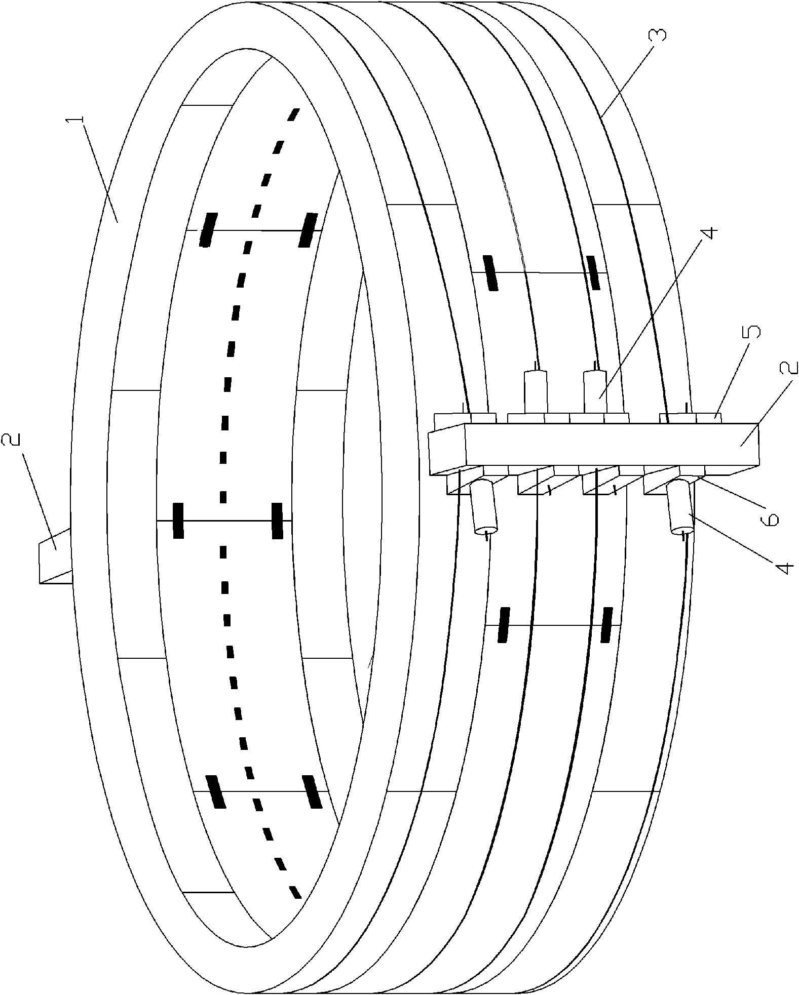
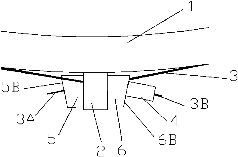
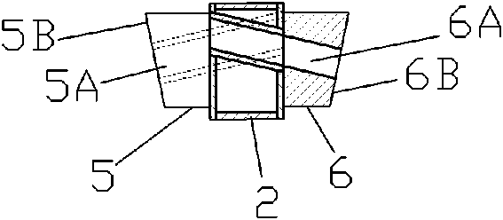
[0021] Figure 1-3 Shown, a kind of embodiment of the present invention is: a kind of shield tunnel structure prototype test water pressure application device, is provided with hoop beam 2 longitudinally on the outer peripheral surface of shield tunnel structure prototype 1, hoop anchor cable 3 The anchor end 3A passes through the anchor hole on the hoop beam 2, and then circles around the prototype 1 of the shield tunnel structure, and then the jack top 3B passes through the jack hole on the hoop beam 2 and the jack 4 on the side of the hoop beam 2 connected to the ejector rod, which is characterized in that:

[0022] An anchoring backing plate 5 is also provided between the anchoring end 3A of the anchor cable 3 and the anchoring hole, and the anchoring backing plate 5 is provided with an anchoring through hole 5A connected with the anchoring hole. The through hole 5A is inclined, and the angle of inclination makes the anchor cable 3 pass through the anchor hole and the anc...


PUM


Abstract

The invention discloses a test water pressure applying device for a shield tunnel structural model. An anchoring base plate is arranged between an anchoring end and an anchoring hole of an anchor cable; anchoring through holes on the anchoring hole and the anchoring base plate are inclined, and the inclined angles ensure that no inflection points are formed at hole edges when the anchor cable passes through the anchoring hole and the anchoring through holes; the outer side of the anchoring base plate is vertical to the anchoring hole; a jack base plate is arranged between the top of a jack and a jack hole; jack through holes on the jack hole and the jack base plate are inclined, and the inclined angles ensure that no inflection points are formed at hole edges when the cable passes through the jack hole and the jack through holes; and the outer side of the jack base plate is vertical to the jack hole. A tensioning angle and a tensioning gas of the anchor cable of the device are small, and additional concentrated force at a hoop beam is small so that the influence of environmental water pressure on a model tunnel structure can be actually simulated; therefore, more accurate and reliable basis can be provided for the design and construction of the shield tunnel structure, tunnel construction and operation safety can be guaranteed, and the reliability and the safety of the device are high.

Description

technical field [0001] The invention relates to a shield tunnel segment structure prototype test device, in particular to a shield tunnel structure prototype test water pressure application device. Background technique [0002] The application of water pressure to the prototype segment structure of the shield tunnel can be realized by using a self-anchoring hoop device, that is, two hoop beams are vertically arranged on the outer peripheral surface of the shield tunnel structure prototype, and one side of the hoop beam is set There is a hoop jack, the anchor end of the hoop anchor cable fixed on the hoop beam passes through the anchor hole on the hoop beam, and after going around the prototype of the shield tunnel structure for a week, the top end of the jack passes through the hoop beam The jack hole of the jack is connected with the jack rod of the hoop jack. Among them, the hoop beam provides pressure through the hoop anchor cable to simulate and control the structural w...

Claims


Application Information

Patent Timeline
Patent Type & Authority Patents(China)
IPC IPC(8): G01M99/00
Inventor 何川封坤王士民
Owner SOUTHWEST JIAOTONG UNIV
Learn More