Building roof leakage detection device and method

A detection device and roof technology, applied in the direction of detecting the appearance of fluid at the leakage point, using liquid/vacuum degree for liquid tightness measurement, etc., can solve the problems of steel corrosion, high equipment cost, high detection efficiency, etc., and achieve hardware saving cost, reduce device volume, and improve detection efficiency

Active Publication Date: 2020-12-22
ZHEJIANG COLLEGE OF CONSTR
View PDF10 Cites 1 Cited by
  • Summary
  • Abstract
  • Description
  • Claims
  • Application Information

AI Technical Summary

Problems solved by technology

[0002] At present, in the process of housing construction, due to the unreasonable selection of materials, the lack of rigorous and scientific construction methods, and the proliferation of counterfeit and inferior products, the leakage of housing construction in my country is very prominent.
Leakage in the house will cause mold on the wall, and the leaking water will cause dampness and mildew on the surface of the indoor wall paint, wallpaper, etc., which will lead to mildew, peeling and other phenomena in the surrounding furniture and solid wood floors, which directly affect the living aesthetics of the environment
At the same time, in the case of continuous leakage, the structure of the house is eroded, the steel bars are corroded, the structural bearing capacity is greatly reduced, and the overall safety of the house is greatly damaged, which eventually makes it difficult for the service life of the house to reach the reasonable use of its design. number of years
[0003] At present, there are mainly two types of methods used in roof leak detection. One is to use high-pressure gas or liquid to inject into the roof gap, and then use the sensor equipment that cooperates with the gas or liquid to detect its flow direction and position, so as to determine Roof leakage, this type of detection method has high detection efficiency, but the operation is complicated, the equipment cost is high, and it can only detect specific roof leakage; the second type is a more traditional detection method, that is, injecting water on the roof. Manually observe the pattern formed after the water seepage to determine the location and intensity of the leak. This type of detection method is simple to operate and low in cost, but the detection efficiency is low. Since the roof seepage usually needs to be observed for several days, it takes a long time to manually observe the leak. Time-consuming and labor-intensive, it takes several days to complete, and often only a simple leak result can be obtained a few days later, and it is difficult to obtain the development of the entire leak

Method used


Image

  • Building roof leakage detection device and method
  • Building roof leakage detection device and method
  • Building roof leakage detection device and method

Examples


Embodiment 1

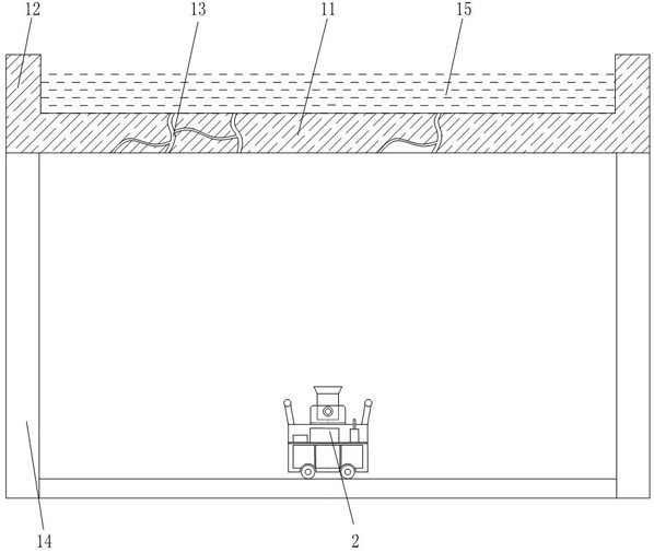
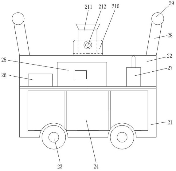
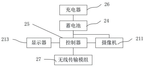
[0034] Such as Figure 1 to Figure 3 As shown, a building roof leakage detection device of the present invention includes a main detection device 2, and the main detection device 2 includes a casing, wheels 23, batteries 24, controllers 25, chargers 26, wireless transmission modules 27, poles Support 28, pole 29, camera support frame 210, camera 211 and display 213, shell comprises lower shell 21 and upper shell 22, and upper shell 22 is arranged on the top of lower shell 21, forms an upper installation chamber in the upper shell 22, and lower shell A lower installation chamber is formed in 21, and four universal wheels 23 are symmetrically arranged on the bottom of lower housing 21 . The storage battery 24 wherein is arranged in the lower installation room, and the storage battery 24 supplies power for the entire building roof leakage detection device. The storage battery 24 in the present embodiment uses a large capacity of 24 ~ 48v, a rechargeable lithium battery, a control...

Embodiment 2

[0043] Such as Figure 4 to Figure 7 As shown, on the basis of the structure in Embodiment 1, a building roof leakage detection device of the present invention also includes a plurality of sub-camera assemblies 3, and a plurality of sub-camera assemblies 3 can be placed on the top of the upper casing 22, each sub-camera Assembly 3 includes a sub-camera support frame 310, a sub-camera 311 and a sub-camera base 313. The sub-camera 311 is installed in the sub-camera support frame 310, and the sub-camera support frame 310 is fixed on the upper end of the sub-camera base 313. The sub-camera 311 communicates with the controller through wires. 25 connections, the work of multiple sub-cameras 311 can be controlled by one controller 25. The sub-camera assembly 3 also includes a sub-camera angle adjustment knob 312. The sub-camera 311 is installed in the sub-camera support frame 310 through the sub-camera angle adjustment knob 312. The adjustment knob 312 adjusts. By arranging a plura...


PUM


Abstract

The invention relates to the technical field of roof leakage detection, and discloses a building roof leakage detection device and method. A main detection device comprises a housing, wheels, a storage battery, a controller, a charger, a wireless transmission module group, a holding rod support, a holding rod, a camera support frame, a camera, and a display. The housing comprises an upper housingand a lower housing. The upper housing is arranged on the upper portion of the lower housing, an upper installation chamber is formed in the upper housing, a lower installation chamber is formed in the lower housing, a plurality of wheels are symmetrically arranged at the bottom of the lower housing, the storage battery is arranged in the lower installation chamber, the controller, the charger andthe wireless transmission module are installed in the upper installation chamber, and the storage battery supplies power to the whole main detection device, and the charger is connected with the storage battery through a wire. Continuous online detection of building roof leakage can be achieved, the continuous development situation of roof leakage is obtained, time is saved, and the device is easy to operate and low in use cost.

Description

technical field [0001] The invention relates to the technical field of roof leakage detection, in particular to a building roof leakage detection device and detection method. Background technique [0002] At present, in the process of housing construction, due to the unreasonable selection of materials, the lack of rigorous and scientific construction methods, and the proliferation of counterfeit and inferior products, the leakage problem of housing construction in my country is very prominent. Leakage in the house will cause mold on the wall, and the leaking water will cause dampness and mildew on the surface of the indoor wall paint, wallpaper, etc., which will lead to mildew, peeling and other phenomena in the surrounding furniture and solid wood floors, which directly affect the living The aesthetics of the environment. At the same time, in the case of continuous leakage, the structure of the house is eroded, the steel bars are corroded, the structural bearing capacity ...

Claims


Application Information

Patent Timeline
Patent Type & Authority Applications(China)
IPC IPC(8): G01M3/04
CPCG01M3/04
Inventor 邵伟芳张智靓吴利燕
Owner ZHEJIANG COLLEGE OF CONSTR
Why Eureka
Try Eureka