Supercharge Your Innovation With Domain-Expert AI Agents!

Chip detection device and chip detection method

A chip inspection and chip technology, applied in the field of chip inspection device and chip inspection, can solve the problems of low efficiency, high manufacturing cost, complicated fixture design, etc., and achieve the effect of simplifying the operation process, improving the efficiency and reducing the inspection cost.

Pending Publication Date: 2020-12-22
SHENZHEN RAYBOW OPTOELECTRONICS
View PDF0 Cites 1 Cited by
  • Summary
  • Abstract
  • Description
  • Claims
  • Application Information

AI Technical Summary

Problems solved by technology

[0006] The invention provides a chip detection device and a chip detection method to solve the technical problems of complex fixture design, high manufacturing cost, complex manual detection process and low efficiency in the prior art

Method used


Image

  • Chip detection device and chip detection method
  • Chip detection device and chip detection method
  • Chip detection device and chip detection method

Examples


Embodiment Construction

[0031] The following will clearly and completely describe the technical solutions in the embodiments of the present invention with reference to the accompanying drawings in the embodiments of the present invention. Obviously, the described embodiments are only some, not all, embodiments of the present invention. Based on the embodiments of the present invention, all other embodiments obtained by persons of ordinary skill in the art without making creative efforts belong to the protection scope of the present invention.

[0032] It should be noted that if there is a directional indication (such as up, down, left, right, front, back...) in the embodiment of the present invention, the directional indication is only used to explain the position in a certain posture (as shown in the accompanying drawing). If the specific posture changes, the directional indication will also change accordingly.

[0033] In addition, if there are descriptions involving "first", "second" and so on in ...


PUM


Abstract

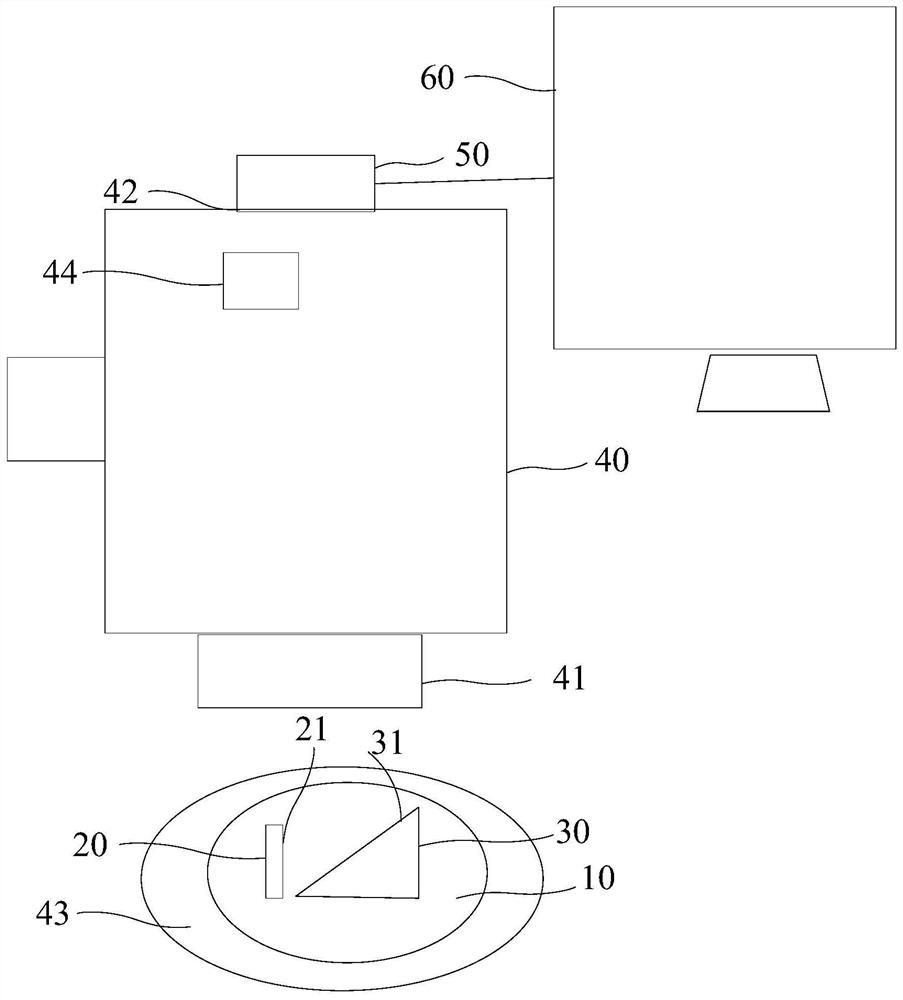
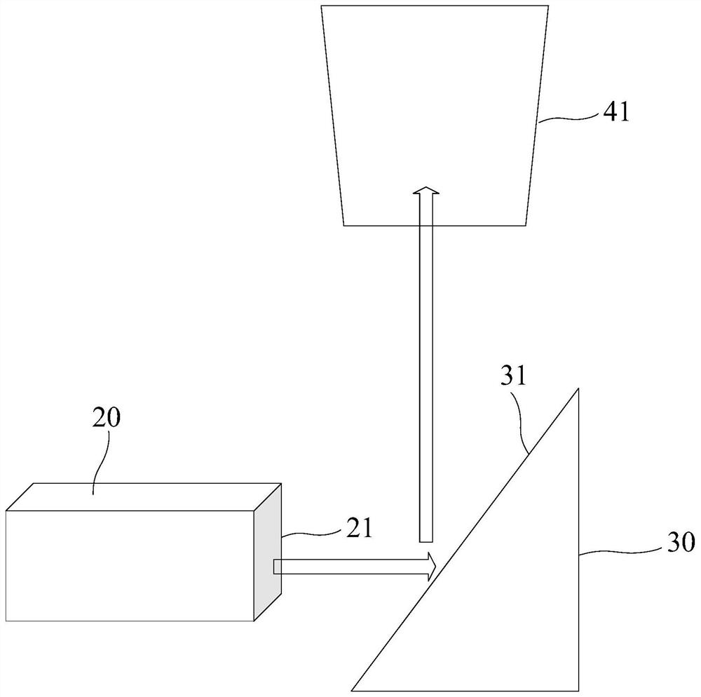
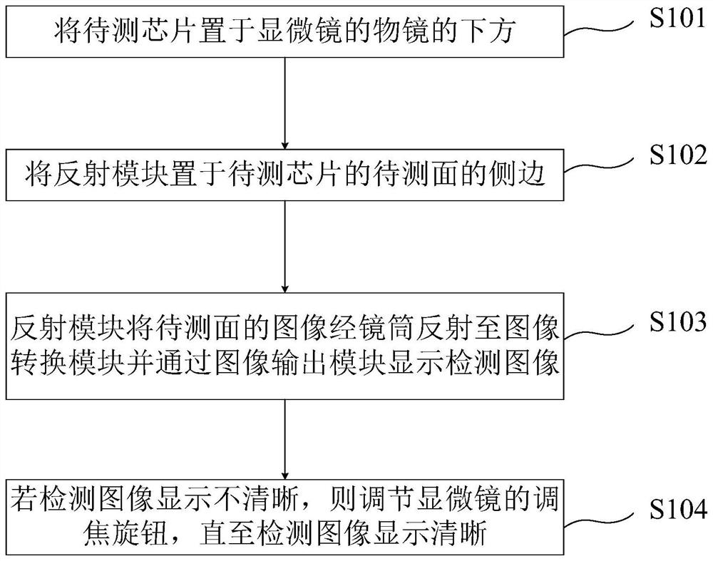
The invention provides a chip detection device. The device comprises a chip bearing module, a reflection module, a microscope, an image conversion module and an image output module, the chip bearing module is used for bearing the bottom of a to-be-detected chip, the side surface of the to-be-detected chip is a to-be-detected surface, the reflection module is arranged at the side edge of the to-be-detected surface, and the microscope comprises an objective lens and a lens. The objective lens is used for being arranged above the reflection module, the image conversion module is arranged at the outer end of a lens cone, and the image output module is electrically connected with the image conversion module. According to the chip detection device and method provided by the invention, the imageof the to-be-detected surface of the to-be-detected chip is reflected to the image conversion module through the reflection module, and the detection image is displayed through the image output module, so that the cavity surface of the chip on a wafer expanding ring can be directly detected without taking down the chip from the wafer expanding ring when the chip is manually detected, the operationprocess is simplified, the efficiency of the detection process is improved, complex detection tools are not needed, and the detection cost is reduced.

Description

technical field [0001] The invention relates to the field of semiconductor chip detection, in particular to a chip detection device and a chip detection method. Background technique [0002] In the manufacturing process of semiconductor lasers, it is necessary to visually sort the appearance of the cavity surface of the chip on the wafer, that is, to inspect the cavity surface of each chip in the chip under a microscope to observe whether there is contamination on the surface of the cavity surface. [0003] The existing method of visually inspecting the chip cavity surface is: pick up the expanded chip with a suction pen, place it on the chip carrier of the visual inspection fixture in turn, and rotate the chip carrier to align the cavity surface of the chip. microscope objective. But existing technology has the following problems: [0004] The fixture design is complicated, the precision requirement is high, and the manufacturing cost is high; [0005] During manual oper...

Claims


Application Information

Patent Timeline
Patent Type & Authority Applications(China)
IPC IPC(8): G01N21/94G01N21/01
CPCG01N21/94G01N21/01
Inventor 赵楚中吴淑娟
Owner SHENZHEN RAYBOW OPTOELECTRONICS
Features
  • R&D
  • Intellectual Property
  • Life Sciences
  • Materials
  • Tech Scout
  • Unparalleled Data Quality
  • Higher Quality Content
  • 60% Fewer Hallucinations
Learn More