
Dust filter bag for vacuuon cleaner

A technology for dust filter bags and vacuum cleaners, applied in the direction of vacuum cleaners, suction filters, applications, etc., can solve problems such as expensive solutions, and achieve the effect of large resilience

Inactive Publication Date: 2003-09-17
VORWERK & CO INTERHOLDING GMBH
View PDF2 Cites 1 Cited by
  • Summary
  • Abstract
  • Description
  • Claims
  • Application Information

AI Technical Summary

Problems solved by technology

and this solution is quite expensive

Method used


Image

  • Dust filter bag for vacuuon cleaner
  • Dust filter bag for vacuuon cleaner
  • Dust filter bag for vacuuon cleaner

Examples


Embodiment Construction

[0043] The dust filter bag 1 depicted in the figures is a so-called single-use or disposable bag.

[0044] For this purpose, the installation chamber 2 of the vacuum cleaner 3 is used for an exchangeable dust filter bag 1 . It can be seen from Fig. 23 that the vacuum cleaner may involve a hand-held vacuum cleaner. A blower 4 in the form of a motor / blower assembly, electrically driven by a power supply or a battery, is housed in a chamber 5 which is detachable from the housing 2 or is separate therefrom. The support wall of the dust filter bag 1 , which is indicated as air-permeable, is denoted by 6 in the figure. Mounted on the support wall 6 is a tuyere 7 passing through it, the tuyere 7 being connected to the suction channel 8 . The suction channel 8 communicates with the suction nozzle 9 . Below the blower 4 there is an upwardly open deflector 10 . There is an exhaust air filter 11 below the deflector 10 . The air outlet is connected to it.

[0045] The connecting sid...


PUM


Abstract

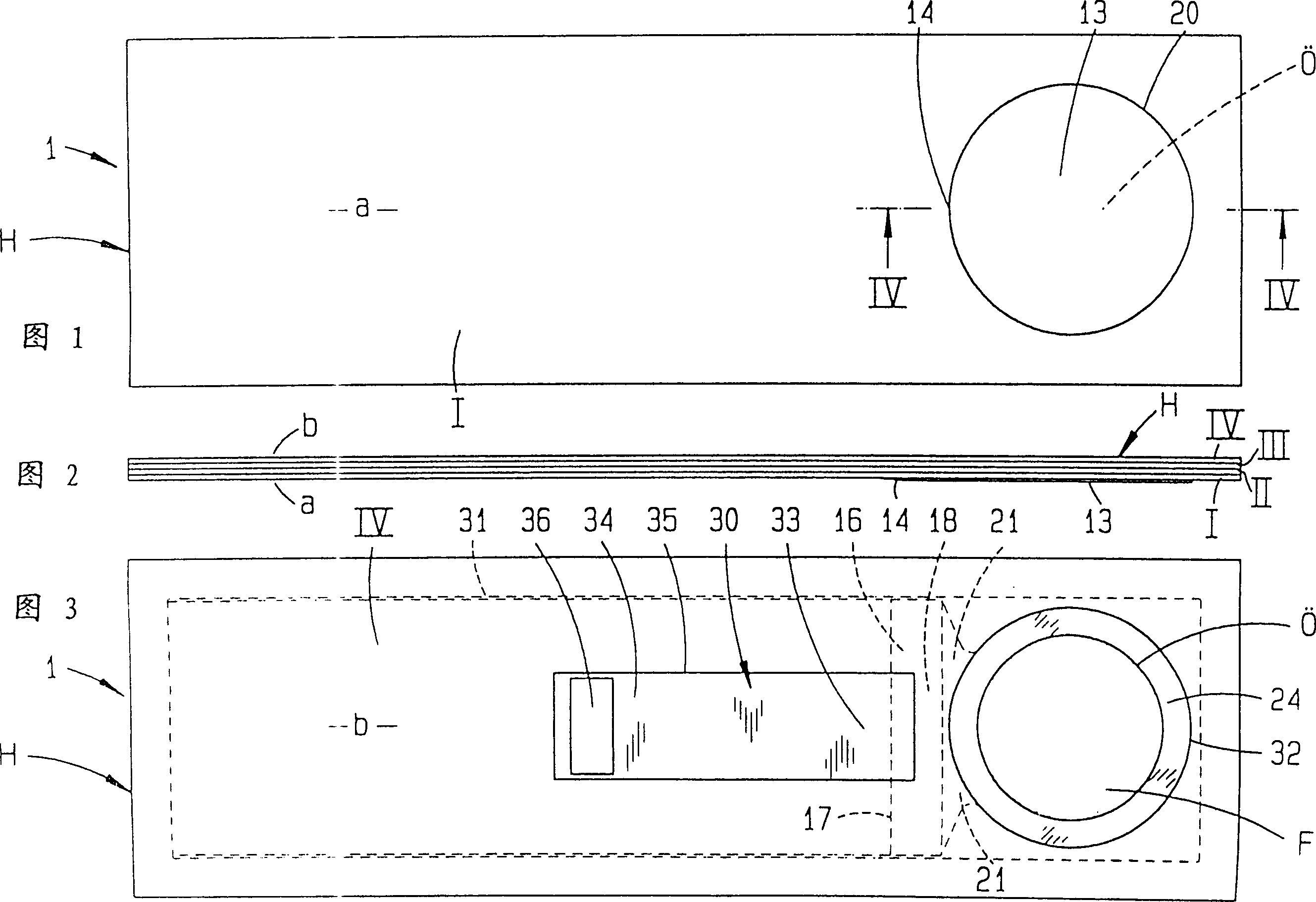
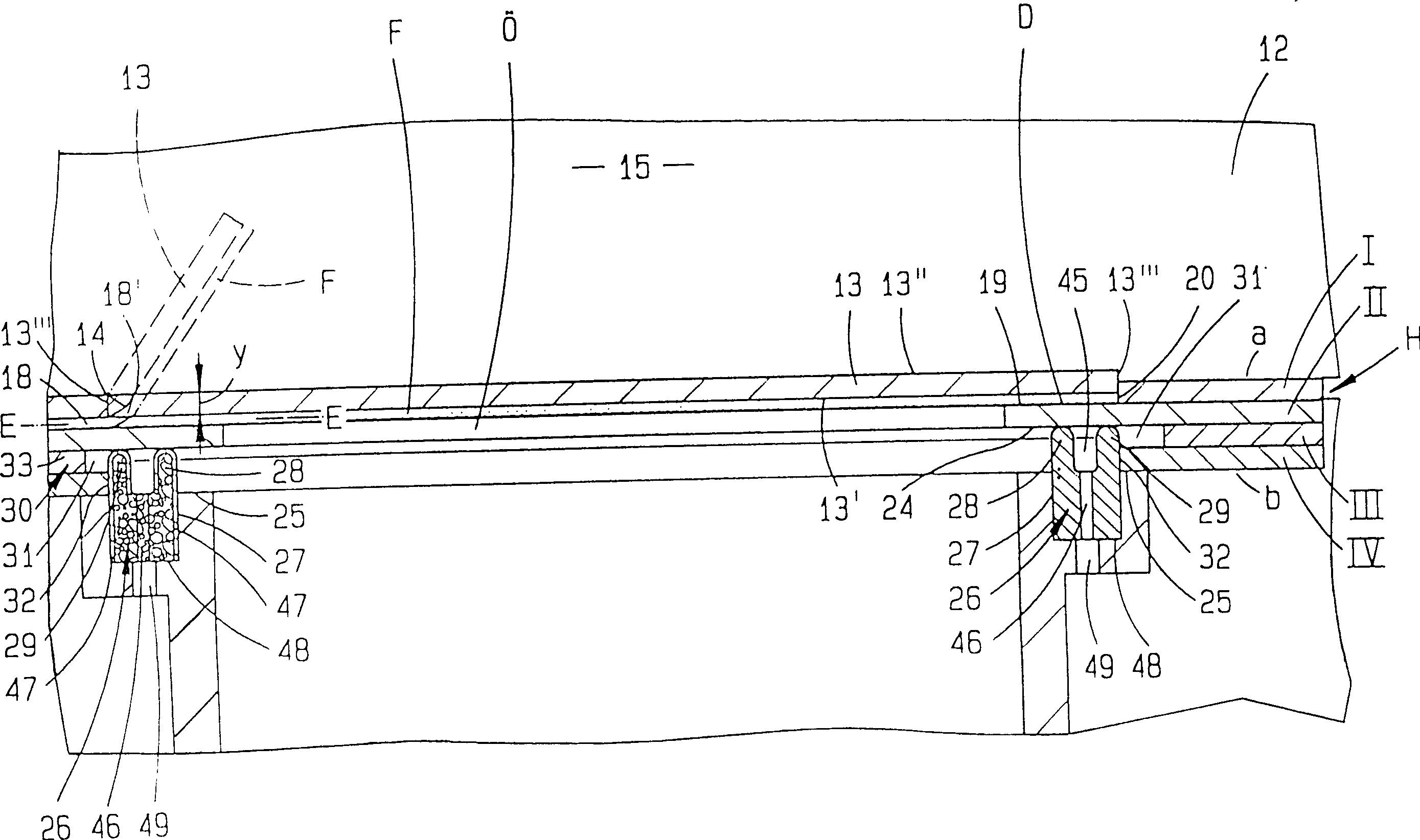
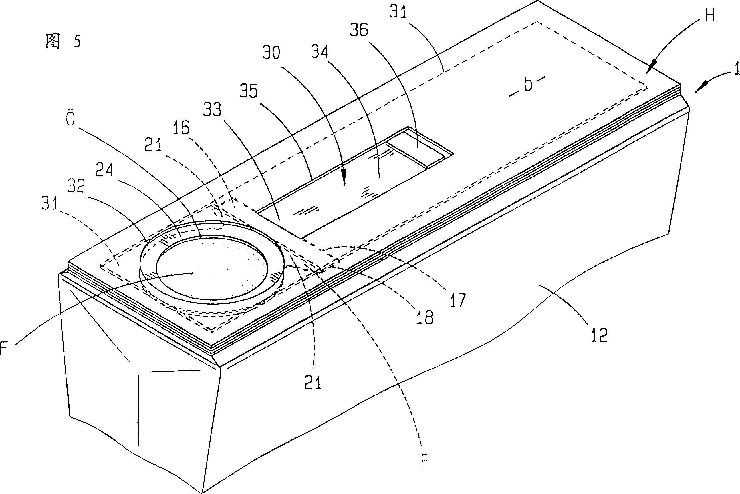
PCT No. PCT / EP95 / 01528 Sec. 371 Date Jan. 21, 1997 Sec. 102(e) Date Jan. 21, 1997 PCT Filed Apr. 22, 1995 PCT Pub. No. WO95 / 29621 PCT Pub. Date Nov. 9, 1995A dust filter bag (1) for a vacuum cleaner (3), with a retaining plate (H). The bag is constructed of a solid paper material, such as cardboard for example, to which a dust bag (12) is joined, for example adhesively, with a closure flap (13) turned towards the inside (15) of the dust bag (12), hinged on the retaining plate (H), which closure flap (13) is openable against a spring action and, in closed condition, keeps closed an opening (O) in the retaining plate (H). To make the dust filter bag simpler in construction and more advantageous as regards use, a band-like spring element (F) is attached to the closure flap (13) in such a way that, in the closed condition (FIG. 4), there is formed a clearance (Y) between a band end (E-E) and a hinge axis (14), lying outside of the band, of the closure flap (13), where the hinge axis (14) is provided turned towards the inside (15) of the dust bag (1).

Description

technical field [0001] The present invention relates to a dust filter bag for a vacuum cleaner, which has a fastening plate made of firm paper material such as cardboard, to which the dust bag is bonded, for example; The flap can be opened against the elastic force and covers a hole in the fixed plate in the closed state. Background technique [0002] Such a dust filter bag is known from US-PS 2070674. Facing the inside of the dust collecting bag, the flap is hinged on the fixed plate to cover the hole, and is suspended on the hinge connected with the fixed plate. Insert a guarded nozzle through the hole. It protrudes in the direction of the vacuum cleaner air duct, and in this direction shrinks into a funnel shape. A tuyere is inserted floatingly into the funnel hole. The edge protector is used as the support of the nozzle at the edge of the hole through its surface on one side of the fixed plate, and the surface facing the inside of the dust bag plays the role of the f...

Claims


Application Information

Patent Timeline
Patent Type & Authority Patents(China)
IPC IPC(8): A47L9/14
CPCA47L9/1445A47L9/1454A47L9/14
Inventor 保罗·利纳恩卢克斯蒂芬·克劳特-赖恩科伯尔
Owner VORWERK & CO INTERHOLDING GMBH
Learn More