Portable display device for construction drawings of construction site

A display device, construction site technology, applied in furniture parts, applications, household appliances, etc., can solve the problems of inconvenient operation and transportation, and achieve the effect of good support and portable transportation.

Active Publication Date: 2020-12-25
安徽筑恒建设有限公司
View PDF11 Cites 2 Cited by
  • Summary
  • Abstract
  • Description
  • Claims
  • Application Information

AI Technical Summary

Problems solved by technology

[0006] In order to overcome the shortcomings of the above-mentioned devices in the above-mentioned patents, which are relatively large overall and relatively inconvenient during operation and transportation, the technical problem to be solved by the present invention is to provide a construction site construction with a smaller overall device that makes manual handling more portable. Portable display device for drawings

Method used


Image

  • Portable display device for construction drawings of construction site
  • Portable display device for construction drawings of construction site
  • Portable display device for construction drawings of construction site

Examples


Embodiment 1

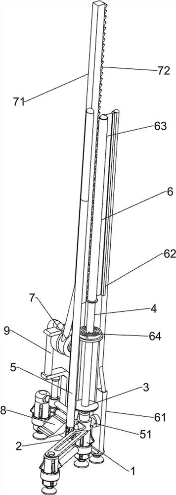
[0027] A portable display device for construction drawings on a construction site, such as Figure 1 to Figure 3 As shown, it includes a support column 1, a first connecting rod 2, a fixed rod 3 and a rotating rod 4, and the first connecting rod 2 is connected between the three supporting columns 1, and the two first connecting rods are arranged in front and back in 2 points, and the three supporting rods The columns 1 are distributed in a triangular shape, the top of the support column 1 in the middle is connected with a fixed rod 3, and the fixed rod 3 is connected with a rotating rod 4 in a rotatable manner, and also includes a guide assembly 5, a pulling assembly 6 and a clamping assembly 7. A guide assembly 5 is provided between the support column 1 and the fixed rod 3 , a pull-out assembly 6 is provided between the rotating rod 4 and the guide assembly 5 , and a clamping assembly 7 is provided between the fixed rod 3 and the pull-out assembly 6 .

[0028] The guide assem...

Embodiment 2

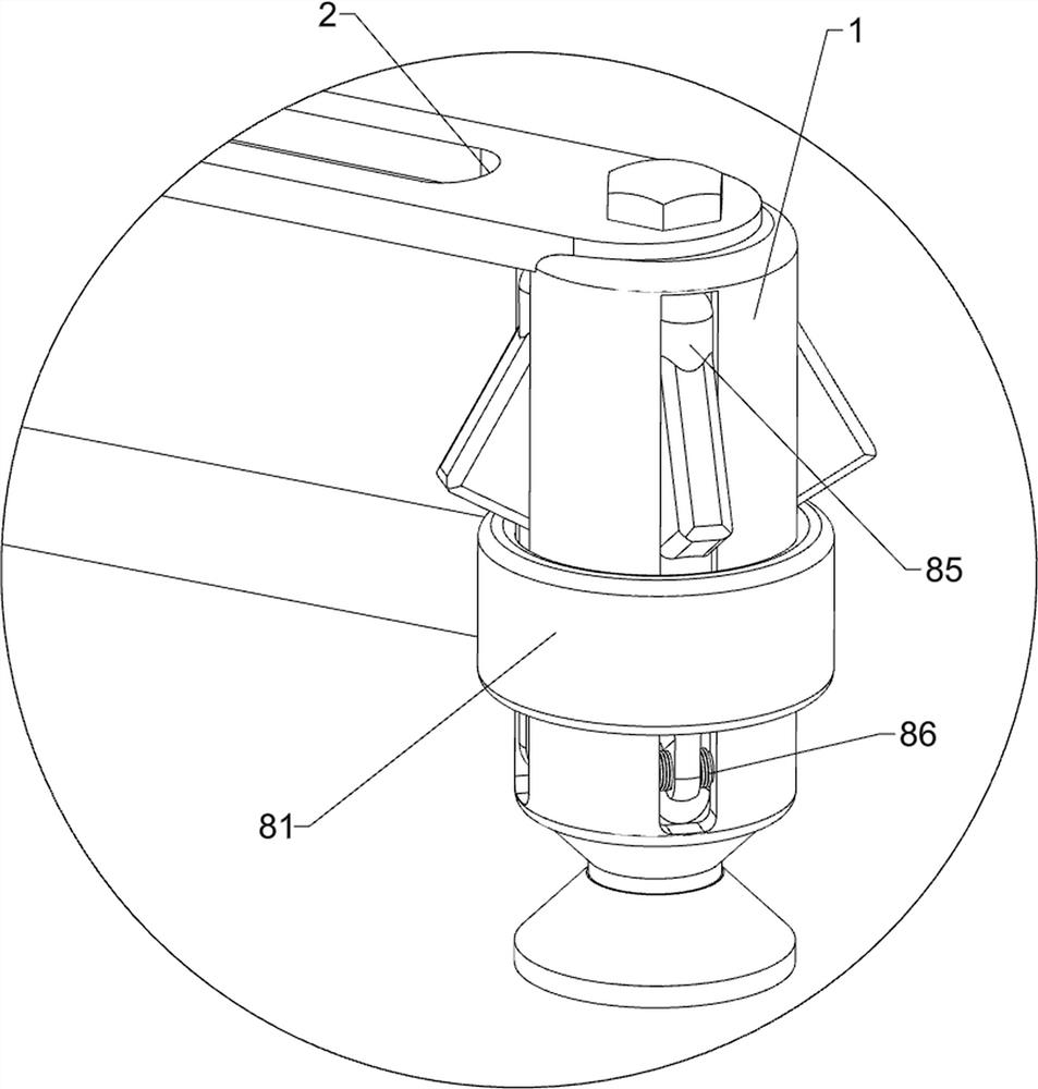
[0033] On the basis of Example 1, such as Figure 4 to Figure 6 As shown, a stabilizing assembly 8 is also included, and the stabilizing assembly 8 includes a sliding ring 81, a sliding rod 82, a return spring 83, a wedge block 84, a pole 85 and a third torsion spring 86, and the three supporting columns 1 are all slidably connected. Sliding ring 81 is arranged, between the sliding ring 81 on the front side and the sliding ring 81 in the middle part and between the sliding ring 81 on the rear side and the sliding ring 81 in the middle part are all connected with sliding rods 82, and the two sliding rods 82 are arranged front and back. The rear sliding bar 82 is slidingly matched with the first connecting rod 2 on the rear side, a return spring 83 is connected between the first connecting rod 2 on the rear side and the sliding bar 82 on the rear side, and a wedge block 84 is connected to the left side of the fixed frame 74. The wedge-shaped block 84 cooperates with the rear sid...

Embodiment 3

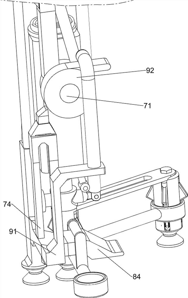
[0036] On the basis of Example 2, such as Figure 4 and Figure 6 As shown, it also includes a retractable assembly 9, the retractable assembly 9 includes a push plate 91, a rotating disk 92 and a connecting plate 93, the fixed frame 74 is connected with a push plate 91, and the transmission shaft of the swing frame 71 is connected with a rotating disk 92, A connection plate 93 is connected to the turntable 92 , and the connection plate 93 cooperates with the push plate 91 .

[0037]Initially, the second torsion spring 76 is in a compressed state. When the connection seat 61 moves to the right, the push plate 91 is driven by the fixed mount 74 to move to the right. After the push plate 91 moves to the right, it no longer resists the connection plate 93. At this time Under the action of the second torsion spring 76, the swing frame 71 swings and resets. When there is no need to display the construction drawings, the swing frame 71 can be pulled to reset, and the second torsion...


PUM


Abstract

The invention relates to a display device, in particular to a portable display device for construction drawings of a construction site. The technical problem to be solved by the invention is how to design the portable display device for the construction drawings of the construction site, wherein the portable display device is smaller in overall size and is more portable during manual carrying. Inorder to solve the technical problem, the portable display device for the construction drawings of the construction site comprises three supporting columns, wherein a first connecting rod is connectedamong the three supporting columns, and the three supporting columns are distributed in a triangular shape; a fixing rod connected to the top of the supporting column in the middle, and a rotating rod is connected to the fixing rod in a rotary-type mode; and a guide assembly is arranged between the supporting column in the middle and the fixing rod. Drawing is displayed through cooperative operation of the guide assembly, a pull-open assembly and a clamping assembly, and therefore the drawing display effect is achieved.

Description

technical field [0001] The invention relates to a display device, in particular to a portable display device for construction drawings of a construction site. Background technique [0002] With the continuous development of modern science and technology, in modern society, buildings are becoming more and more beautiful. When building a building, it is usually necessary to draw the construction drawings. After the construction drawings are drawn, the staff need to follow the construction drawings To carry out construction, so it is necessary to display the construction drawings, so that the construction personnel can display according to the construction drawings. [0003] After retrieval, the authorized patent publication number is CN110680106A, which discloses a drawing display device, including a support, and the lower part of the support is provided with a fastening structure and a clamping paper structure, and the fastening structure is used to display the drawing. The ...

Claims


Application Information

Patent Timeline
IPC IPC(8): A47B97/02
CPCA47B97/02
Inventor 廖秀连
Owner 安徽筑恒建设有限公司
Why Eureka
Try Eureka