[0023] The technical solutions in the embodiments of the present invention will be clearly and completely described below with reference to the accompanying drawings in the embodiments of the present invention. Obviously, the described embodiments are only a part of the embodiments of the present invention, but not all of the embodiments. Based on the embodiments of the present invention, all other embodiments obtained by those of ordinary skill in the art without creative efforts shall fall within the protection scope of the present invention.
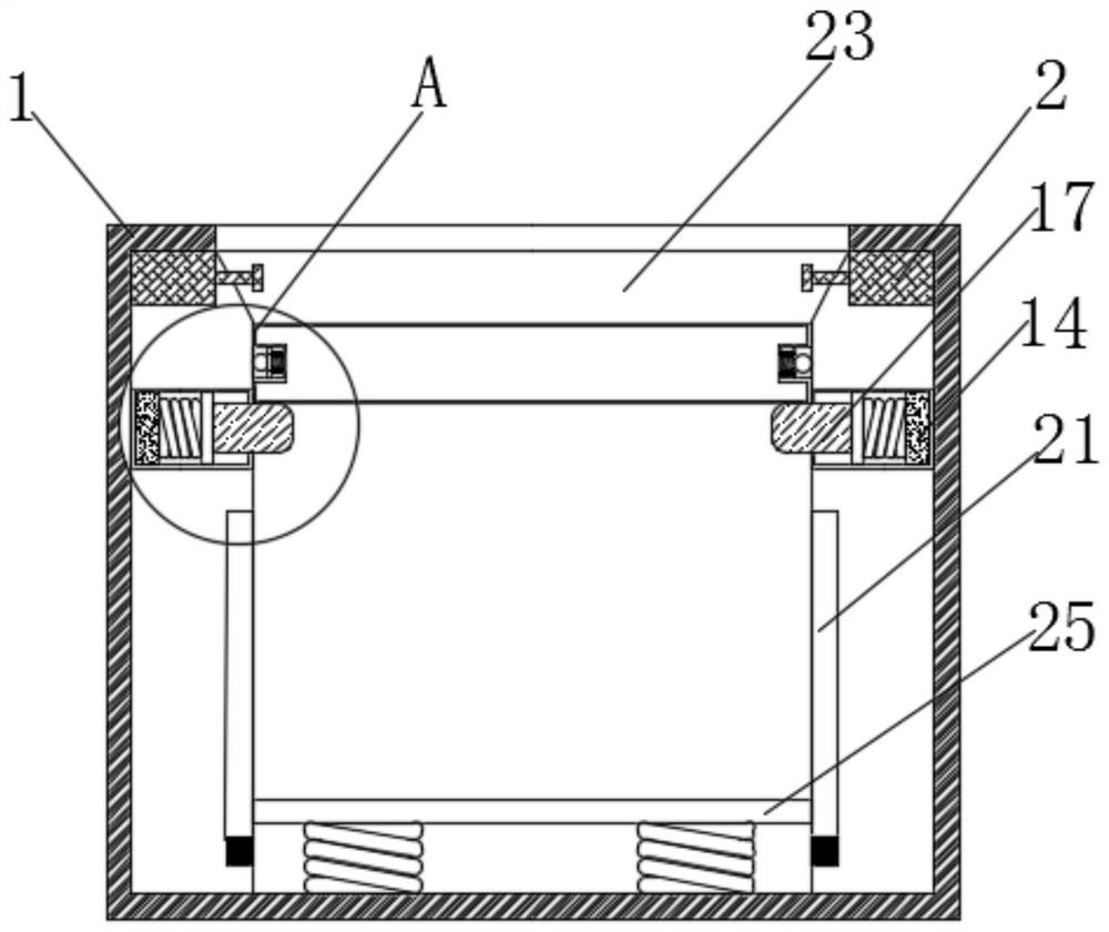
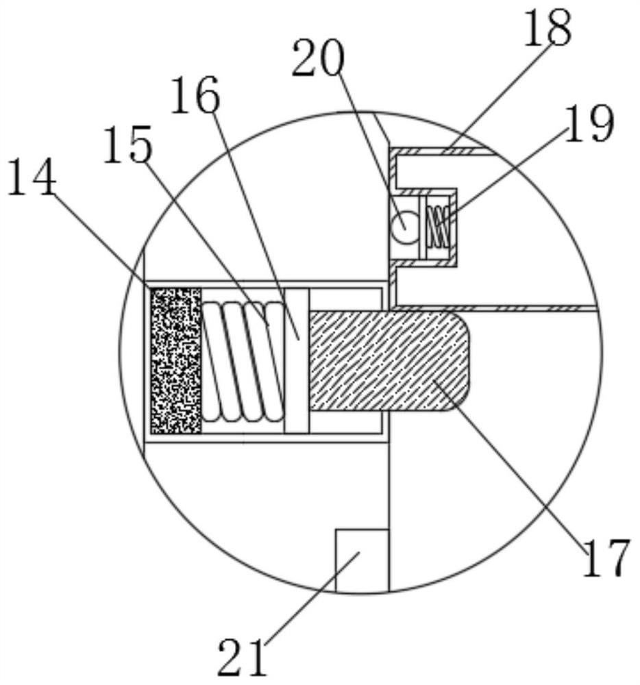
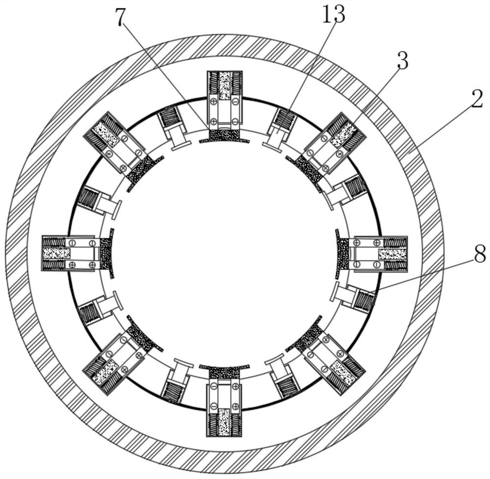
[0024] see Figure 1-5 , an intelligent handicraft display stand with tilt warning, including a casing 1, a detection device 2 is fixedly connected to the upper end of the casing 1, a first enclosure 3 is fixedly connected inside the detection device 2, and the first enclosure 3 and the second enclosure are 8. Symmetrically arranged inside the detection device 2, through the first enclosure 3 to detect whether the handicraft is in a tilted state, when the tilt occurs, the capacitance on the positive electrode plate 5 and the negative electrode plate 6 will increase, and the current will also increase. , the current flows to the joint 11 on the electro-variable 9 through the wire 12, so that the solution of the electro-variable 9 becomes solid, and the position of the second push block 13 in the fixed electro-variable 9 is reached, preventing the craft from continuing to tilt.
[0025] A dielectric plate 4 is fixedly connected inside the first casing 3 , a positive electrode plate 5 is arranged on the left side of the dielectric plate 4 , the size of the positive electrode plate 5 and the negative electrode plate 6 are the same, and the The distance is greater than the size of the dielectric plate 4. As the relative area between the dielectric plate 4 and the positive electrode plate 5 and the negative electrode plate 6 increases, the capacitance on the positive electrode plate 5 and the negative electrode plate 6 increases, which is consistent with the expected capacitance. By comparison, the pre-warning is turned on, a negative electrode plate 6 is arranged on the right side of the dielectric plate 4, a first push block 7 is fixedly connected to the end of the negative electrode plate 6 away from the dielectric plate 4, and a second envelope is arranged on both sides of the first envelope 3 8. An electro-current variant 9 is arranged inside the second enclosure 8, a first spring 10 is arranged on the surface of the electro-mechanical variant 9, and the end of the first spring 10 close to the inner wall of the second enclosure 8 is fixedly connected with a joint 11, and the surface of the joint 11 is fixed A wire 12 is connected, one end of the first spring 10 away from the inner wall of the second enclosure 8 is fixedly connected with a second push block 13 , and an electromagnetic device 14 is provided at the bottom of the detection device 2 .
[0026] The magnetic pole of the magnetic field generated by the electromagnetic device 14 is opposite to the magnetic pole of the first magnet block 16 on the opposite surface. The electromagnetic device 14 drives the third push block 17 to move by attracting the first magnet block 16, so that the third push block 17 loosens its grip on the working platform 18. Fixed, the surface of the electromagnetic device 14 is fixedly connected with the second spring 15, the end of the second spring 15 away from the electromagnetic device 14 is fixedly connected with the first magnetic block 16, the surface of the first magnetic block 16 is fixedly connected with the third push block 17, the third The upper end of the push block 17 is provided with a working platform 18, a third spring 19 is fixedly connected inside the working platform 18, and one end of the third spring 19 away from the inner wall of the working platform 18 is fixedly connected with a second magnet block 20, and the surface of the second magnet block 20 is on the first A slot 21 is slidably connected, and the magnetic pole of the second magnet block 20 is the same as that of the third magnet block 22 on the opposite surface. The third magnet block 22 repels the second magnet block 20 on the working platform 18 to make the The handicraft can stay on the first longboard 25 slowly.
[0027] The bottom of the third push block 17 is provided with a first notch 21 , a third magnetic block 22 is fixedly connected inside the casing 1 and inside the first notch 21 , and a second notch 23 is opened in the middle of the casing 1 . The inner second slot 23 is provided with round holes on both sides of the upper end, and the first push block 7 and the second push block 13 monitor and fix the state of the handicrafts on the working platform 18 through the round holes, so as to protect the handicrafts, A fourth spring 24 is fixedly connected inside the casing 1 and at the bottom of the second slot 23 , and a first long plate 25 is fixedly connected to one end of the fourth spring 24 away from the inner wall of the casing 1 .
[0028]Working principle: The intelligent handicraft display stand with tilt warning, first place the handicraft on the working platform 18, when the display stand is collided, the handicraft tilts and squeezes the first push block 7 and the second push block 13, the first push block 7 and the second push block 13. The block 7 drives the positive electrode plate 5 and the negative electrode plate 6 to slide in the first enclosure 3. As the relative area between the dielectric plate 4 and the positive electrode plate 5 and the negative electrode plate 6 increases, the dielectric constant increases. , so the capacitance on the positive electrode plate 5 and the negative electrode plate 6 will increase, and the external circuit is compared with the predetermined capacitance value to determine whether the warning is turned on. 12 flows to the joint 11 on the surface of the electro-mechanical variant 9, so that the electro-mechanical variant 9 is energized from liquid to solid, thereby fixing the position of the second push block 13 on the electro-mechanical variant 9, preventing the craft from continuing to tilt, according to the collision of the craft. , intelligently send out an early warning signal according to the capacitance change in the detection device 2, and at the same time control the fixation of the second push block 13 to protect the handicraft.
[0029] Secondly, the current flows to the electromagnetic device 14 through the external circuit, so that the electromagnetic device 14 is energized, and the magnetic pole of the magnetic field generated by the electromagnetic device 4 is opposite to the magnetic pole of the first magnet block 16 on the opposite surface. The electromagnetic device 14 drives the third pusher by attracting the first magnet block 16 The block 17 moves, so that the third push block 17 loosens the fixation on the working platform 18, so that the working platform 18 slides in the second slot 23 inside the casing 1, and at the same time, under the action of the third spring 19, the second magnetic The block 20 slides in the first slot 21 inside the casing 1. The magnetic pole of the second magnet block 20 is the same as that of the third magnet block 22 on the opposite surface. The second magnet block 20 and the third magnet block 22 repel each other, so that the working platform The handicrafts on 18 can slowly drop to the first long board 25 to protect the handicrafts. At the same time, the bottom end of the first long board 25 is fixedly connected with a fourth spring 24, which further relieves the impact force of the handicrafts falling, so that the handicrafts can smoothly descend. frame, to prevent the phenomenon of handicraft being damaged.
[0030] Although embodiments of the present invention have been shown and described, it will be understood by those skilled in the art that various changes, modifications, and substitutions can be made in these embodiments without departing from the principle and spirit of the invention and modifications, the scope of the present invention is defined by the appended claims and their equivalents.