Postoperative rehabilitation exercise device for breast surgery

An exercise device and breast surgery technology, applied in sports accessories, training equipment for adjusting the cardiovascular system, training equipment for adjusting coordination, etc., can solve the problem that the patient's upper limb rehabilitation exercise cannot achieve the expected effect and affect the patient's quality of life. Patients can not persist for a long time and other problems, to achieve the effect of novel structure, convenient exercise, simple and convenient operation

Active Publication Date: 2020-12-25
NANYANG CITY CENT HOSPITAL
19 Cites 3 Cited by

AI-Extracted Technical Summary

Problems solved by technology

[0002] With the development of society, people are living in a fast pace of life, and the pressure of life is gradually increasing. Most women live irregularly in daily life. The incidence of breast cancer is increasing year by year, and it is beginning to tend to be younger. Surgery is still the main method for the treatment of breast cancer. However, after the operation, most of the affected sides generally suffer from postoperative diseases such as upper limb dysfunction and lymphedema, which seriously...

Method used

As shown in Figure 17 and Figure 18, when rectangular gear block 6 is engaged with rectangular rack 5, adjustment handrail 3 can be fixed, and parallel rod 7 forms a parallelogram structure, so that rectangular gear block 6 can always move In a parallel state, when controlling the height of the adjustable armrest 3, the handle 11 can be moved by hand, and the parallel pull rod 7 is driven by moving the handle 11 to rotate around the hinge point hinged with the bottom of the adjustable armrest 3 and drive the rectangular tooth block 6 Move upwards, when the rectangular tooth block 6 moves upwards, the reset slider 9 can be pushed to move by the reset push rod 8 and the return spring 10 can be squeezed. When the rectangular gear is separated from the rectangular rack 5, the height of the adjustment armrest 3 can be adjusted. Adjustment, when the height adjustment of the armrest 3 is adjusted, the handle 11 is released, the return spring 10 can push the reset slider 9 to reset, and the rectangular gear block 6 is re-engaged with the rectangular rack 5 through the linkage of the reset push rod 8 The adjustable armrest 3 is fixed, and both the adjustable armrest 3 and the fixed armrest are used to facilitate the patient to support the patient's upper limbs when getting up, and by lowering the height of the adjustable armrest 3, the mounting plate 27 can be conveniently moved to the upper end of the seat 1, which is convenient for the patient to perform exercise.
When this device is in use, the patient can sit on the table and chair surface, turn over the mounting plate 27 to the upper side of the seat 1, carry out activities and exercise the upper limbs by the exercise box 29, promote the recovery of the patient's upper limb function, and when exercising The exercise box 29 can be adjusted to a tilted state to facilitate the exercise of the affected limb and increase the comfort of the affected limb during exercise. The four corners of the bottom of the seat 1 are respectively fixedly connected with foot brake universal wheels for conveniently moving the device; The non-circular parts of 34 are respectively rotated and connected with an exercise h...

Abstract

The invention relates to a postoperative rehabilitation exercise device for the breast surgery, which is characterized in that a backrest capable of overturning forwards and backwards is mounted at the rear end of a seat, a height-adjustable adjusting armrest is mounted on the left side of the upper end of the seat, a mounting plate capable of overturning to the upper end of the seat is mounted onthe left side of the seat, and an exercise box capable of sliding forwards and inclining is mounted on the surface of the upper end of the mounting plate; and exercise discs capable of moving front and back and rotating during moving are slidably connected to the left side and the right side of the upper end surface of the exercise box correspondingly. When the device is used, a patient can sit on the surface of the table and chair, the mounting plate is turned over to the upper side of the chair, the upper limbs are moved and exercised through the exercising box, recovery of the upper limb function of the patient is promoted, the exercising box can be adjusted to be in an inclined state during exercising, affected limbs can be exercised conveniently, and the comfort of the affected limbsduring exercising is improved; when the patient performs rehabilitation exercise on the upper limbs, the exercise modes can be switched, so that the patient can use different exercise modes for exercise during rehabilitation exercise, and the exercise effect of the patient is enhanced.

Application Domain

Space saving gamesMovement coordination devices +1

Technology Topic

Surgery.breastRehabilitation exercise +6

Image

  • Postoperative rehabilitation exercise device for breast surgery
  • Postoperative rehabilitation exercise device for breast surgery
  • Postoperative rehabilitation exercise device for breast surgery

Examples

  • Experimental program(1)

Example Embodiment

[0043] The following are specific embodiments of the present invention, and the technical solutions of the present invention will be further described with reference to the accompanying drawings, but the present invention is not limited to these embodiments.
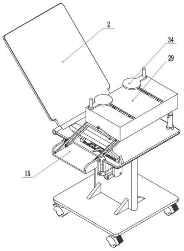
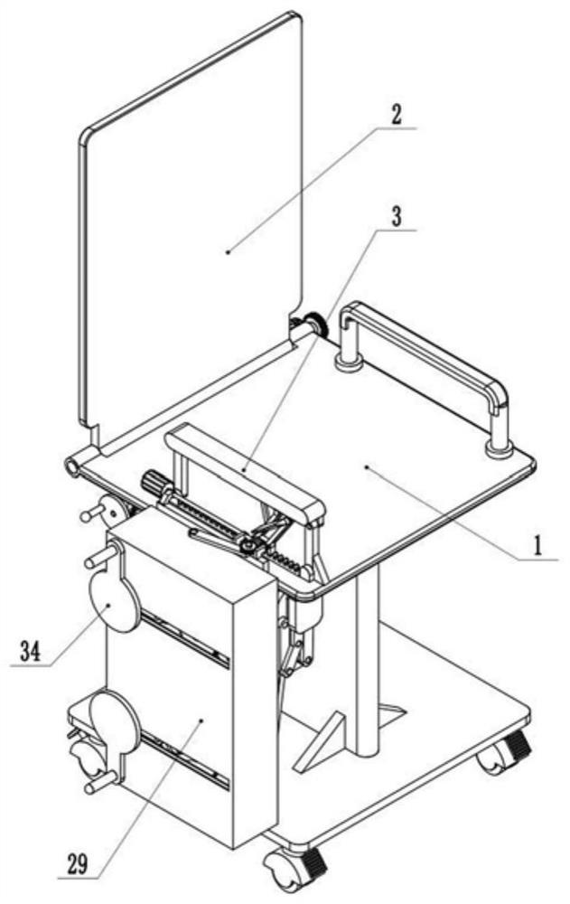
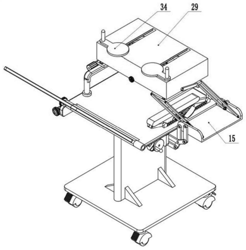
[0044] like Figure 1-20 As shown, the present invention provides a postoperative rehabilitation exercise device for breast surgery, comprising a seat 1, a backrest 2 that can be turned back and forth is installed at the rear end of the seat 1, and a backrest 2 that can be turned upside down is installed at the rear end of the seat 1. A height-adjusting armrest 3, the left side of the seat 1 is installed with a mounting plate 27 that can be turned over to the upper end of the seat 1, and the upper end surface of the mounting plate 27 is installed with an exercise that can slide and tilt forward Box 29, the left and right sides of the upper end surface of the exercise box 29 are respectively slidingly connected with exercise discs 34 that can move back and forth and rotate when moving;
[0045] The left and right sides of the inside of the exercise box 29 are respectively fixedly connected with a fixed gear 39, the middle upper side of the fixed gear 39 is rotatably connected with a triangular coupling frame 40, and the edge of the fixed gear 39 is engaged with the transmission gear 38, so The transmission gear 38 is rotatably connected with the triangular coupling frame 40, the edge of the transmission gear 38 is engaged with the exercise gear 37, the exercise gear 37 is rotatably connected with the triangular coupling frame 40, and the exercise gear 37 is rotatably connected with the triangular coupling frame 40. The upper side is coaxially fixed with a link rod 36 , and the other end of the link rod 36 is fixedly connected with the exercise plate 34 . When the triangular link frame 40 rotates around the center of the fixed gear 39 A structure in which the exercise plate 34 moves back and forth and rotates at the same time can be constructed; a drive structure for driving the triangular coupling frame 40 to rotate is installed inside the exercise box 29 .
[0046] When the device is in use, the patient can sit on the surface of the table and chair, turn the mounting plate 27 to the upper side of the seat 1, and use the exercise box 29 to move and exercise the upper limbs, so as to promote the recovery of the patient's upper limb function, and can exercise The box 29 is adjusted to the inclined state, which is convenient for exercising the affected limb and increases the comfort of exercising the affected limb. The four corners of the bottom of the seat 1 are respectively fixed with foot brake universal wheels, which are used to facilitate the movement of the device; The circular parts are respectively connected with exercise grips, and the patient can use both hands to hold the exercise grips when exercising, and drive the triangular coupling frame 40 to rotate through the driving structure, such as Figure 5 and Figure 17 As shown, the left and right sides of the upper end of the exercise box 29 are respectively provided with chute channels, the inside of the chute channel is slidably connected with the installation slider 35, the middle of the lower end of the exercise plate 34 is fixedly connected with the installation shaft, and the lower end of the installation shaft is connected with the linkage rod 36 is fixedly connected, the length of the link rod 36 is equal to the length from the center of the exercise gear 37 to the center of the fixed gear 39, and the center of the fixed gear 39 corresponds to the chute channel, which will drive the exercise gear when the triangular coupling frame 40 rotates. 37 and the transmission gear 38 rotate around the fixed gear 39 and the length of the middle part of the exercise gear 37 and the fixed gear 39 is constant, and then the exercise plate 34 can be driven to rotate when the exercise gear 37 is driven to rotate under the transmission of the transmission gear 38. At the same time, it moves back and forth along the chute channel, so that the affected limb moves while holding the handle with both hands and making circles during exercise, which increases the exercise range of the patient's upper limb and enhances the patient's exercise effect; the left and right sides of the lower end of the backrest 2 A hinge shaft is fixedly connected to the side respectively, the hinge shaft is hinged with the rear end of the seat 1, the surface of the hinge shaft on the right side is fixedly connected with an adjusting worm gear 12, and the lower side of the adjusting worm gear 12 is engaged with an adjusting worm 13, and the adjusting worm 13 is rotatably connected to the seat 1. On the surface of the seat 1, the front end of the adjusting worm 13 is fixedly connected with an adjusting knob 14. By turning the adjusting knob 14 to drive the adjusting worm 13 to rotate, the adjusting worm wheel 12 can be driven to rotate. The user's comfort when leaning on the backrest 2 has various functions.
[0047] The drive structure includes a rotatable driving bevel gear 59 , a mounting bracket 45 is arranged on the rear side of the driving bevel gear 59 , the mounting bracket 45 is fixedly connected inside the exercise box 29 , and the middle of the fixed gear 39 is A connecting shaft is rotatably connected, the upper end of the connecting shaft is fixedly connected with the triangular coupling frame 40, and the lower surface of the connecting shaft is rotatably connected with the mounting frame 45;
[0048] The middle part of the mounting frame 45 is fixedly connected to a limiting cylinder 46 , the interior of the limiting cylinder 46 is slidably connected with an inner sheave 47 that can move up and down, and a matching inner shaft 51 is rotatably connected to the inside of the inner sheave 47 . The lower end of the matching inner shaft 51 is rotatably connected to the inner lower end of the exercise box 29, the lower surface of the matching inner shaft 51 is fixedly connected with a rotating worm wheel 53, and the edge of the rotating worm wheel 53 is engaged with a rotating worm 54, so The rotating worm 54 is rotatably connected inside the exercise box 29, the front end of the rotating worm 54 penetrates the exercise box 29, and a rotating knob 55 is fixedly connected to the front end of the rotating worm 54;
[0049] The inner wall of the inner sheave 47 is provided with a wave-shaped driving inner groove 50, the upper end of the matching inner shaft 51 is fixedly connected to the matching pin shaft 52 on both sides, and the outer end of the matching pin shaft 52 is respectively connected with the driving shaft 52. The inner groove 50 is slidably connected, and when the matching inner shaft 51 rotates, the inner groove wheel 47 can move up and down to form a structure.
[0050] A motor 60 is fixedly connected to the front side of the driving bevel gear 59, and when the motor 60 rotates, the driving bevel gear 59 can be driven to rotate; the patient has two different exercise methods when exercising with this device, and two different exercise methods are used When switching, the inner sheave 47 is moved up and down by rotating the matching inner shaft 51. When switching, the rotating knob 55 is controlled to rotate and the matching inner shaft 51 is driven to rotate under the meshing action of the rotating worm 54 and the rotating worm wheel 53, and the matching inner shaft 51 is rotated. When the shaft 51 rotates, it can drive the inner sheave 47 to move up and down by cooperating with the pin shaft 52 and the driving inner groove 50, such as Figure 12 As shown in the figure, the inner sheave 47 is slidably connected to the inside of the limit cylinder 46, the limit chutes are respectively provided on both sides of the surface of the inner sheave 47, and the limit chutes are respectively provided on the inner surface of the limit cylinder 46 to cooperate with the limit chutes. The slider, the inner sheave 47 can only move up and down under the restriction of the limiting cylinder 46, and the driving inner groove 50 has a wave-shaped structure, Figure 12 The middle inner sheave 47 is at the uppermost side, and the matching pin shaft 52 is at the lowermost side of the driving inner groove 50. When rotating the matching inner shaft 51, the inner sheave 47 can be driven downward by sliding connection with the matching pin shaft 52 and the driving inner groove 50. Move, and then switch the exercise mode.
[0051] The left and right sides of the mounting frame 45 are respectively rotatably connected with a second transmission pulley 42, the lower end of the connecting shaft is fixedly connected with a first transmission pulley 41, and the surface of the first transmission pulley 41 is respectively covered with a transmission belt. The other end of the second transmission pulley 42 is respectively sleeved with the second transmission pulley 42, and the upper and lower ends of the second transmission pulley 42 are respectively fixedly connected with an upper connecting end gear 43 and a lower connecting end gear 44;
[0052] The lower side of the driving bevel gear 59 is meshed with a lower connecting bevel gear 56 , the middle of the lower connecting bevel gear 56 is fixedly connected with a lower connecting pipe 49 , and the matching inner shaft 51 is rotatably connected inside the lower connecting pipe 49 , the upper end of the lower connecting pipe 49 is rotatably connected with the bottom of the inner sheave 47, the lower surface of the lower connecting pipe 49 is fixedly connected with an active dial 57, and the left and right sides of the active dial 57 are meshed respectively. There is a sheave 58, the middle of the sheave 58 is slidably connected with a first limit rod, and the first limit rod is rotatably connected with the inner wall of the exercise box 29. The active dial 57 and the two grooves The lower side of the wheel 58 is respectively connected with a first connecting plate in common rotation, and the upper side of the sheave 58 is respectively fixedly connected with a first transmission end face gear 62, and the first transmission end face gear 62 is respectively connected with all the upper side gears. The lower connecting end face gear 44 is engaged.
[0053] The upper end of the inner sheave 47 is rotatably connected with an upper connecting pipe 48 , and the surface of the upper connecting pipe 48 is fixedly connected with an upper connecting bevel gear 63 that can mesh with the driving bevel gear 59 . The upper side of the surface is fixedly connected with the interlocking gear 64, the two sides of the interlocking bevel gear are respectively meshed with the auxiliary interlocking gear 65, and the upper sides of the interlocking gear 64 and the two auxiliary interlocking gears 65 rotate respectively. A second connecting plate is connected; the middle part of the auxiliary link gear 65 is slidably connected with a second limit rod, and the upper end of the second limit rod is rotatably connected with the mounting frame 45;
[0054] The lower ends of the auxiliary interlocking gears 65 are respectively fixedly connected with second transmission face gears 66 that can mesh with the upper connecting face gears 43 .
[0055] like Figure 11 , Figure 13 and Figure 14As shown, the initial state of the device is that the inner sheave 47 is at the uppermost side, the lower connecting bevel gear 56 meshes with the driving bevel gear 59, and the first transmission face gear 62 meshes with the lower connecting face gear 44 respectively. During the rotation, the driving wheel 57 can be driven to rotate under the transmission of the lower connecting bevel gear 56. When the driving wheel 57 is rotated, the two sheaves 58 can be driven to rotate alternately and intermittently. When rotating, the power can be transmitted to the triangular coupling frame 40 through the meshing of the first transmission end face gear 62 and the lower connecting end face gear 44 to drive the triangular coupling frame 40, so that the two triangular coupling frames 40 rotate alternately and intermittently, Then, the affected limbs can alternately draw circles and move alternately with both hands during exercise, so that the patient's upper limbs can be adaptively exercised during the exercise teeth, and the comfort of the patient during use can be enhanced; the first coupling plate is used to drive the active The dial 57 and the sheave 58 can move synchronously. The first limit rod is used to provide a mounting part for the sheave 58 to move up and down. When the exercise mode needs to be switched, it can drive the inner groove 50 and the sheave 47 to move down and drive the active waves. The cassette sheave 58 moves downward synchronously, so that the first transmission face gear 62 is disengaged from the lower connecting face gear 44, and the lower connecting bevel gear 56 is disengaged from the driving bevel gear 59; Figure 15 As shown, when the inner sheave 47 moves downward, the first transmission end gear 62 is disengaged from the lower connecting end gear 44, and the second transmission end gear 66 can be engaged with the upper connecting end gear 43, and the upper connecting cone The gear 63 can mesh with the driving bevel gear 59, and when the driving bevel gear 59 rotates, it can drive the interlocking gear 64 to rotate through the transmission of the upper connecting bevel gear 63, and drive the two auxiliary gears through the transmission of the interlocking gear 64. The interlocking gear 65 rotates synchronously, and moves the two triangular coupling frames 40 to rotate synchronously through the meshing transmission of the upper connecting end gear 43 and the second transmission end gear 66, so that the hands of the affected limb can continue to draw circles. It moves back and forth to enhance the patient's exercise intensity; the second coupling plate is used to drive the interlocking gear 64 and the auxiliary interlocking gear 65 to move synchronously when the inner sheave 47 moves downward.
[0056] The left and right sides of the surface of the mounting plate 27 are respectively slidably connected with inclined sliders 28 , and the upper ends of the inclined sliders 28 are hinged with the bottom of the exercise box 29 respectively; the rear sides of the left and right ends of the mounting plate 27 are respectively rotated Connected with an inclined support rod 30, the upper ends of the inclined support rods 30 are respectively inclined forward and hinged with the surface of the exercise box 29, and the lower end of the left inclined support rod 30 is coaxially fixed with a control worm gear 31 The lower side of the control worm gear 31 is engaged with a control worm 32, the rotation of the control worm 32 is connected to the left end surface of the mounting plate 27, and the front end of the control worm 32 is fixedly connected with a control knob 33.
[0057] When using the exercise box 29, the exercise box 29 can be adjusted to be inclined according to the patient's wishes, so as to facilitate the exercise of the affected limb; during adjustment, the control worm 32 can be driven to rotate by rotating the control knob 33, and the control worm 32 and the control worm wheel can be adjusted. Under the engagement of 31, the tilt rod 30 is turned upward. When the tilt rod 30 is turned upward, the rear side of the installation box can be moved to the front side and the front side of the installation box is driven to tilt upward. The patient can adjust the adjustment by turning the control knob 33. The angle at which the exercise box 29 is tilted.
[0058] The left side of the seat 1 is installed with a mounting frame plate 15 that can be turned upward, and the front and rear end surfaces of the mounting frame plate 15 are respectively hinged with a second parallel bending rod 21 and a second parallel hinge rod 22 that are parallel to each other. The lower ends of the second parallel hinged rods 22 are respectively hinged with first parallel bending rods 20 , and the bent portions of the first parallel bending rods 20 and the second parallel bending rods 21 are hinged to each other, and the second parallel bending rods 21 are hinged to each other. The lower end of the rod 21 is hinged with a first parallel hinge rod 19 , the first parallel hinge rod 19 and the first parallel bending rod 20 are parallel to each other, and the first parallel hinge rod 19 and the first parallel bending rod 20 are parallel to each other. The other end is hinged with the seat 1 respectively, and the first parallel hinge rod 19 at the rear end is fixedly connected with the hinge point of the seat 1 coaxially with a driving worm wheel 18, and the upper side of the driving worm wheel 18 is fixed coaxially. A drive worm 17 is engaged, the drive worm 17 is rotatably connected to the lower side of the seat 1 , and a drive turntable 16 is fixedly connected to the left end of the drive worm 17 .
[0059] A second parallel rod 26 and a first parallel rod 25 are respectively hinged on the left side of the front and rear end surfaces of the mounting plate 27 from left to right, and the second parallel rod 26 and the first parallel rod 25 are parallel to each other. The lower ends of the second parallel rods 26 and the first parallel rods 25 are respectively hinged on the inner side surface of the mounting bracket plate 15 , and the lower ends of the first parallel rods 25 are respectively fixedly connected with driven pinions 24 . The upper sides of 24 are respectively meshed with large transmission gears 23 , and the large transmission gears 23 are respectively coaxially and fixedly connected with the second parallel hinge rods 22 .
[0060] like figure 2 As shown, the first parallel bending rod 20, the second parallel bending rod 21, the first parallel hinge rod 19, the second parallel hinge rod 22 and the first parallel rod 25 when the exercise box 29 is retracted to the left side of the seat 1 , the second parallel rods 26 are all in a folded state, such as image 3 , Figure 4 , Figure 5 and Image 6 As shown, the first parallel bending rod 20, the second parallel bending rod 21, the first parallel hinge rod 19, and the second parallel hinge rod 22 form two sets of parallelogram structures. The meshing of the worm gear 18 drives the first parallel hinged rod 19 to rotate, so that the first parallel bending rod 20, the second parallel bending rod 21, the first parallel hinged rod 19, and the second parallel hinged rod 22 form two parallelograms. When unfolding pushes the mounting plate 15 to rotate 90 degrees parallel to the seat 1, when the second parallel hinge rod 22 is unfolded, it can drive the large transmission gear 23 to rotate. 24 meshing drives the driven pinion 24 to rotate, and drives the first parallel rod 25 to rotate through the rotation of the driven pinion 24. The first parallel rod 25 and the second parallel rod 26 form a parallelogram structure. When the first parallel rod 25 rotates Then, the second parallel rod 26 can be driven to rotate synchronously and push the mounting plate 27 to move stably to the right, so that the mounting plate 27 moves to the upper side of the seat 1, and the upper right side of the seat 1 is fixedly connected with a fixed armrest. The mounting plate 27 can be used to support the mounting plate 27, so that the mounting plate 27 can be placed on the upper side of the seat 1 stably. It is convenient for patients to exercise, simple to operate, and easy to use; a rectangular groove is opened on the rear side of the surface of the mounting plate 27 to facilitate the user to exercise and prevent the mounting plate 27 from blocking the patient's body.
[0061] A rectangular rack 5 is fixedly connected to the surface on the left side of the upper end of the seat 1 , and the surfaces of the seat 1 on the front and rear sides of the rectangular rack 5 are respectively hinged with armrest support rods 4 , and the upper end of the armrest support rod 4 is hinged. It is hinged with the adjusting armrest 3, the upper end of the rectangular rack 5 is engaged with a rectangular tooth block 6, and the front and rear sides of the left and right ends of the rectangular tooth block 6 are respectively hinged with parallel rods 7, and the parallel rods 7 are mutually connected. Parallel, the upper ends of the parallel pull rods 7 are hinged with the bottom of the adjusting armrest 3 respectively;
[0062] A reset push rod 8 is hinged to the middle of the parallel pull rod 7 on the rear side of the left end, and a reset slider 9 is hinged to the upper end of the reset push rod 8. The bottom of the adjusting armrest 3 is provided with a reset chute. It is slidably connected with the reset chute, and a reset spring 10 is arranged inside the reset chute. A handle 11 is fixedly connected to the upper end of the parallel pull rod 7 on the front side.
[0063] like Figure 17 and Figure 18 As shown, when the rectangular tooth block 6 is engaged with the rectangular rack 5, the adjusting armrest 3 can be fixed, and the parallel rods 7 form a parallelogram structure, so that the rectangular tooth block 6 can always be in a parallel state when moving. The handle 11 can be moved by hand when the height of When moving, the reset push rod 8 can push the reset slider 9 to move and squeeze the reset spring 10. When the rectangular gear is separated from the rectangular rack 5, the height of the adjustment armrest 3 can be adjusted. When the height of the adjustment armrest 3 is adjusted After completion, release the handle 11, the reset spring 10 can push the reset slider 9 to reset, and through the linkage of the reset push rod 8, the rectangular tooth block 6 is re-engaged with the rectangular rack 5 to fix the adjusting armrest 3, and the adjusting armrest is adjusted. 3 and the fixed armrest are both used to facilitate the patient to support the upper limb of the patient when getting up, and by lowering and adjusting the height of the armrest 3, the mounting plate 27 can be moved to the upper end of the seat 1 conveniently, which is convenient for the patient to exercise.
[0064] The specific embodiments described herein are merely illustrative of the spirit of the invention. Those skilled in the art to which the present invention pertains can make various modifications or additions to the described specific embodiments or replace them in similar manners, but will not deviate from the spirit of the present invention or go beyond the definition of the appended claims range.

PUM

no PUM

Description & Claims & Application Information

We can also present the details of the Description, Claims and Application information to help users get a comprehensive understanding of the technical details of the patent, such as background art, summary of invention, brief description of drawings, description of embodiments, and other original content. On the other hand, users can also determine the specific scope of protection of the technology through the list of claims; as well as understand the changes in the life cycle of the technology with the presentation of the patent timeline. Login to view more.

Similar technology patents

Efficient sludge drying treatment device

PendingCN107335279Anovel structureImprove dehydration efficiency
Owner:ZHENGZHOU UNIV

Air purifier capable of automatically removing dust

Owner:JIANGSU CHUANGLAN SOLAR AIR CONDITIONER

Diaryl benzo pyridine derivative, and preparation and use thereof

InactiveCN101463014Ahigh selectivity indexnovel structure
Owner:FUDAN UNIV

Bactericide composition containing coumoxystrobin with synergistic effect

InactiveCN104430357Anovel structureunique mode of action
Owner:JILIN BADA PESTICIDE

Classification and recommendation of technical efficacy words

  • novel structure
  • ingenious idea

Backpack medlar-picking machine

InactiveCN101473731Aeasy to movenovel structure
Owner:CHINA AGRI UNIV

Power storage device and electronic device

ActiveUS20160372717A1high capacitynovel structure
Owner:SEMICON ENERGY LAB CO LTD

Method and device for producing corrugated plate of container

Owner:CHINA INTERNATIONAL MARINE CONTAINERS (GROUP) CO LTD

Measuring device special for architectural design

InactiveCN109855664Aeasy to carryingenious idea
Owner:ZHENGZHOU UNIVERSITY OF AERONAUTICS

Traditional Chinese medicine rehabilitation exercise device for old people nursing

Owner:HENAN PROVINCE HOSPITAL OF TCM THE SECOND AFFILIATED HOSPITAL OF HENAN UNIV OF TCM
Why Eureka
Try Eureka