Plate cutting device for automobile production and machining

A technology for cutting devices and automobiles, which is applied in the direction of shearing devices, metal processing equipment, and accessories of shearing machines. It can solve problems such as the inability to adjust the orientation of cutting devices and affect the use of equipment, and achieve convenient sealing and cutting processing and convenient collection. Handling, Ease of Use Effects

Inactive Publication Date: 2020-12-25
费红
1 Cites 2 Cited by

AI-Extracted Technical Summary

Problems solved by technology

[0003] The currently published Chinese patent authorization announcement number is CN210305973U, a kind of plate cutting device for the processing of the middle plate of the automobile frame. Although the equipmen...

Method used

Described sealing cover 29 middle parts are provided with cutting disk 36, and cutting disk 36 is connected with sealing cover 29 by the 3rd rotating shaft 35, and the 3rd rotating shaft 35 front sides are equipped with the 4th motor 37, and the 4th motor 37 is installed in sealing On the front side of the cover 29, the third rotating shaft 35 and the cutting disc 36 are driven to rotate by the fourth motor 37, so as to facilitate the cutting process of the automobile panels.
Referring to Fig. 1~4, in the embodiment of the present invention, a kind of sheet material cutting device for automobile production and processing comprises support frame 1, and the four corners of described support frame 1 lower side are fixedly installed with support leg 2, and support leg 2 lower side The support block 3 is fixedly installed, which can effectively support the whole equipment. The top of the support frame 1 is provided with a dust collection cover 5, and the support frame 1 located outside the dust collection cover 5 is provided with an annular connection opening 4, which can facilitate the connection between the equipment. connection, so as to facilitate the use of the equipment, a dust suction pipe 6 is installed on the lower side of the dust collection hood 5, a dust suction pump 7 is installed on the dust suction pipe 6, and a dust collection chamber 8 is installed on the lower side of the dust suction pipe 6, with In order to store filtered impurities, the four corners on the upper side of the dust collection chamber 8 are connected to the support frame 1 through the support columns 9, which can facilitate the fixed connection between the support frame 1 and the dust collection chamber 8. The left and right ends of the dust collection chamber 8 are An inclined filter 10 is provided to facilitate the filtering of impurities. Vibrator 11 is installed at the upper and lower ends of the outer side of the inclined filter 10, which can vibrate the impurities attached to the inclined filter 10, so as to facilitate the cleaning of impurities. Vents 12 are installed on the side wall of the central dust collection chamber 8 outside the net 10. During the cutting process, the equipment is vacuumed by the dust suction pump 7, so that the dust generated during the cutting process can be sucked into the dust collection chamber. Inside the chamber 8, after filtering through the inclined filter screen 10, it can facilitate the collection and treatment of impurities and facilitate the use of equipment. A dust discharge pipe 13 is installed on the lower side of the dust collection chamber 8 at the lower side of the inclined filter screen 10. The dust discharge pipe 13 on the lower side of the frame 1 is provided with a control valve 14, which can conveniently control the discharge of impurities.
The present invention drives the second rotating shaft 25 to rotate by the second motor 24, and the second rotating shaft 25 drives the second gear 26 to rotate, because the second gear 26 and the tooth bar 27 are meshed with each other, so will drive the connecting plate 28 And sealing cover 29 moves down, and sealing cover 29 will seal the car sheet material that needs to cut like this, drives the 3rd rotating shaft 35 and cutting disk 36 by the 4th motor 37 and carries out cutting process like this, makes things convenient for the use of equipment like this, and The first motor 19 drives the first gear 17 to rotate, the first gear 17 drives the external gear 20 to rotate, and the external gear 20 drives the rotating pla...

Abstract

The invention relates to the field of automobiles, in particular to a plate cutting device for automobile production and machining. The device comprises a supporting frame; a dust hood is arranged atthe top of the supporting frame; a dust suction pipe is installed at the lower side of the dust hood; a dust collection cavity is installed at the lower side of the dust suction pipe; a supporting rack is installed on the upper side of the supporting frame; connecting grooves are formed in the top of the supporting rack; first gears are arranged inside the connecting grooves and connected with theconnecting grooves through first rotating shafts; the inner sides of the first gears are connected with outer gears; the outer gears are connected with rotating plates through connecting rings; a mounting notch is formed in the interiors of the rotating plates; second motors are mounted inside the mounting notch; second rotating shafts are mounted at the front sides of the second motors; second gears are arranged on the second rotating shafts; racks are meshed with the outsides of the second gears; connecting plates are arranged at the outsides of the racks; a sealing cover is arranged at thelower sides of the connecting plates; and a cutting disc is arranged in the middle of the sealing cover. According to the plate cutting device for automobile production and machining, the device canbe conveniently driven to adjust the angle, so that an automobile plate can be conveniently cut.

Application Domain

Shearing machinesMaintainance and safety accessories +1

Technology Topic

Electric machineryManufacturing engineering +4

Image

  • Plate cutting device for automobile production and machining
  • Plate cutting device for automobile production and machining
  • Plate cutting device for automobile production and machining

Examples

  • Experimental program(2)

Example Embodiment

[0025] Embodiment one
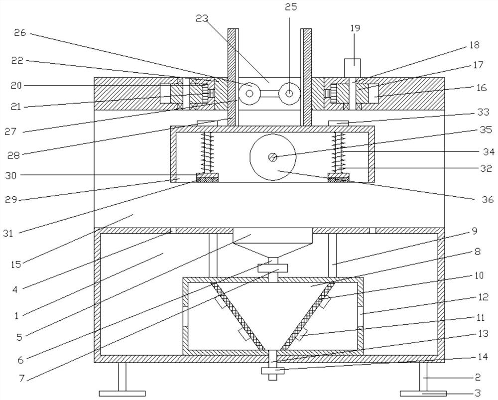
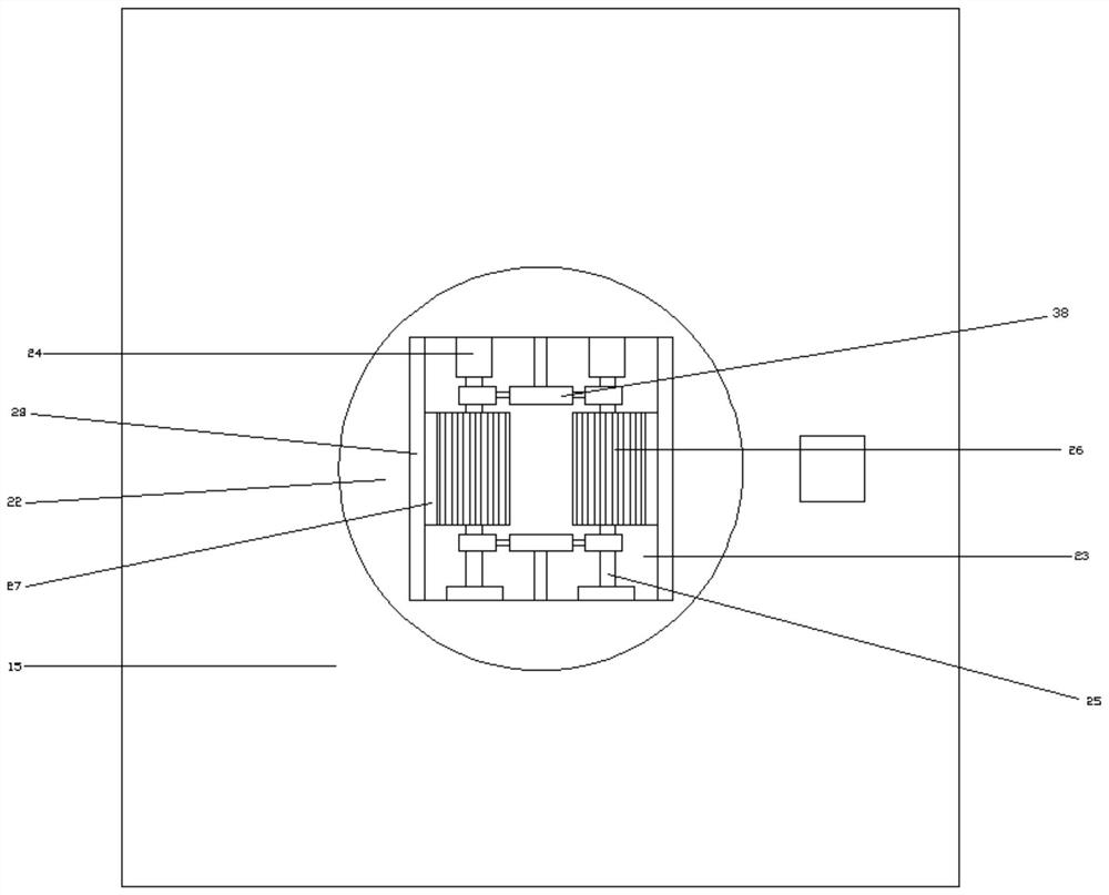
[0026] refer to Figure 1~4 , in an embodiment of the present invention, a plate cutting device for automobile production and processing includes a support frame 1, support legs 2 are fixedly installed at the four corners of the lower side of the support frame 1, and support blocks 3 are fixedly installed on the lower side of the support leg 2, which can Effectively support the entire device, the top of the support frame 1 is provided with a dust cover 5, and the support frame 1 outside the dust cover 5 is provided with an annular connection opening 4, which can facilitate the connection between devices, thereby facilitating the use of the device , the lower side of the dust collection cover 5 is equipped with a dust suction pipe 6, a dust suction pump 7 is installed on the dust suction pipe 6, and a dust collection chamber 8 is installed on the bottom of the dust collection pipe 6, which is used to store filtered impurities and collect dust. The four corners on the upper side of the chamber 8 are connected with the support frame 1 through the support columns 9, which can facilitate the fixed connection between the support frame 1 and the dust collection chamber 8. The left and right ends of the dust collection chamber 8 are provided with inclined filter screens 10, which can To facilitate the filtering of impurities, vibrators 11 are installed at the upper and lower ends of the outer side of the inclined filter screen 10, which can shake off the impurities attached to the inclined filter screen 10, so as to facilitate the cleaning of impurities. The central dust collection chamber located outside the inclined filter screen 10 Vent 12 is installed on the side wall of 8. During the cutting process, the equipment is vacuumed by vacuum pump 7, so that the dust generated during the cutting process can be sucked into the dust collection chamber 8, and the dust can be sucked through the inclined filter screen. 10 After filtering, it is convenient to collect impurities and facilitate the use of equipment. A dust discharge pipe 13 is installed on the lower side of the dust collection chamber 8 located in the middle of the lower side of the inclined filter screen 10, and the dust discharge pipe 13 is located on the lower side of the support frame 1. 13 is provided with a control valve 14, which can conveniently control the discharge of impurities.
[0027] The upper side of the support frame 1 is fixedly equipped with a support frame 15, the top of the support frame 15 is provided with a connecting groove 16, and the left and right ends of the connecting groove 16 are provided with first gears 17, and the first gear 17 connects with the connecting groove through the first rotating shaft 18. 16 for connection, a first motor 19 is installed on the upper side of the first rotating shaft 18 at the right end, and the first motor 19 is fixedly installed on the upper side of the support frame 15, and the inner side of the first gear 17 is threaded with an external gear 20, and the external gear 20 is connected by connecting The ring 21 is connected with the rotating plate 22, the first motor 19 drives the first gear 17 to rotate, the first gear 17 drives the external gear 20 to rotate, and the external gear 20 drives the rotating plate 22 to rotate, so that the orientation of the equipment can be realized , so as to facilitate the cutting process of the automobile sheet and facilitate the use of the equipment, the inside of the rotating plate 22 is provided with a mounting notch 23, and the rear side of the left and right ends of the mounting notch 23 is equipped with a second motor 24, and the front side of the second motor 24 is installed There is a second rotating shaft 25, the front side of the second rotating shaft 25 is connected with the installation notch 23 through the bearing seat, the setting of the bearing seat can facilitate the connection of the second rotating shaft 25, and the second rotating shaft 25 at the front and rear ends are provided with hydraulic brakes 38 , the hydraulic brake 38 is fixedly connected with the installation notch 23 through the connecting piece, the setting of the hydraulic brake 38 can facilitate the braking process on the second rotating shaft 25, thereby facilitating the stability of the equipment, and the second rotating shaft 25 is provided with a second gear 26, the outer side of the second gear 26 is meshed with a rack 27, the outer side of the rack 27 is fixedly installed with a connecting plate 28, and the lower side of the connecting plate 28 is fixedly installed with a sealing cover 29, and the second rotating shaft 25 is driven by the second motor 24 to rotate. The second rotating shaft 25 drives the second gear 26 to rotate, because the second gear 26 and the tooth bar 27 are meshed with each other, so the connecting plate 28 and the sealing cover 29 will be driven to move downward, so that the sealing cover 29 will need to be cut. The automobile sheet is sealed, so that the equipment can be sealed and cut conveniently, and the equipment can be effectively dust-proofed.
[0028] The middle part of the sealing cover 29 is provided with a cutting disc 36, the cutting disc 36 is connected with the sealing cover 29 through the third rotating shaft 35, the fourth motor 37 is installed on the front side of the third rotating shaft 35, and the fourth motor 37 is installed on the sealing cover 29. On the front side, the third rotating shaft 35 and the cutting disc 36 are driven to rotate by the fourth motor 37, so as to facilitate the cutting process of the automobile panels.
[0029]The present invention drives the second rotating shaft 25 to rotate through the second motor 24, and the second rotating shaft 25 drives the second gear 26 to rotate. Since the second gear 26 and the rack 27 mesh with each other, the connecting plate 28 and the sealing cover will be driven like this 29 moves downward, so that the sealing cover 29 will seal the automobile sheet that needs to be cut, and the third rotating shaft 35 and the cutting disc 36 are driven by the fourth motor 37 to cut, which is convenient for the use of the equipment, and through the first The motor 19 drives the first gear 17 to rotate, the first gear 17 drives the external gear 20 to rotate, and the external gear 20 drives the rotating plate 22 to rotate, so that the orientation of the cutting disc 36 can be realized, thereby facilitating the cutting process of the automobile sheet, which is convenient Use of equipment.

Example Embodiment

[0030] Embodiment two
[0031] The difference from Embodiment 1 is that: the bottom of the left and right ends of the sealing cover 29 is provided with an extrusion plate 30, the friction pad 31 is installed on the lower side of the extrusion plate 30, and the front and rear ends of the upper side of the extrusion plate 30 are fixedly installed with connection pads. Rod 32, the upper side of connecting rod 32 is fixedly installed limit block 33, and limit block 33 is installed on the upper side of sealing cover 29, and spring 34 is installed on the connecting rod 32 that is positioned at sealing cover 29 inside, and sealing cover 29 is moving downwards. During the process, the extrusion plate 30 and the friction pad 31 will clamp the automobile sheet to be processed, which can facilitate the cutting of the automobile sheet and facilitate the use of the equipment.

PUM

no PUM

Description & Claims & Application Information

We can also present the details of the Description, Claims and Application information to help users get a comprehensive understanding of the technical details of the patent, such as background art, summary of invention, brief description of drawings, description of embodiments, and other original content. On the other hand, users can also determine the specific scope of protection of the technology through the list of claims; as well as understand the changes in the life cycle of the technology with the presentation of the patent timeline. Login to view more.

Similar technology patents

Disposable medical-examination light

ActiveUS20090097236A1good visualizationeasy to use
Owner:UTAH MEDICAL PRODS

Patient positioning support structure

ActiveUS20120198625A1easy to useinexpensive to make
Owner:WARSAW ORTHOPEDIC INC

Classification and recommendation of technical efficacy words

  • easy to use

Laser assisted total joint arthroplasty

InactiveUS20090234360A1easy to use
Owner:ALEXANDER VLADIMIR

Enclosure for a portable hemodialysis system

ActiveUS20090114582A1easy to use
Owner:DEKA PROD LLP
Why Eureka
Try Eureka