A Pressure Adaptive High Speed ​​Lightweight Underwater Cutting Tool

An underwater cutting and self-adaptive technology, applied in the field of auxiliary equipment for diving operations, can solve the problems of oil leakage or water ingress, inconvenience for divers to work, low reliability, etc., to prevent oil and medium water leakage, and high popularization and application The effect of value, function and easy expansion

Active Publication Date: 2021-08-24
CHINA SHIP SCIENTIFIC RESEARCH CENTER (THE 702 INSTITUTE OF CHINA SHIPBUILDING INDUSTRY CORPORATION)
View PDF0 Cites 0 Cited by
  • Summary
  • Abstract
  • Description
  • Claims
  • Application Information

AI Technical Summary

Problems solved by technology

[0002] At present, most of the cutting tools on the market cannot be directly used by divers underwater. In addition to conventional sealing, material corrosion resistance and structural strength, there are also problems such as heavy weight and inability to adapt to high speed.
In order to adapt to the water pressure at large depths, the casing of cutting tools is usually designed as a pressure-resistant structure or an external oil compensator is added, which will lead to excessive weight of the tool or complex system, which is not convenient for divers to work
When the internal oil filling compensation of the cutting tool, the sealing problem of the external medium water and the internal compensation oil must be considered at the same time. Underwater tools are usually sealed with TC oil seals or rotating grey rings, but TC oil seals are one-way seals, which are not reliable and easy to Faults such as oil leakage or water ingress occur, so it is not suitable for large-depth working environments; the rotating grey ring is a two-way sealing component, but when it is used in high-speed output shaft conditions, the wear is serious and the working life is short

Method used


Image

  • A Pressure Adaptive High Speed ​​Lightweight Underwater Cutting Tool
  • A Pressure Adaptive High Speed ​​Lightweight Underwater Cutting Tool
  • A Pressure Adaptive High Speed ​​Lightweight Underwater Cutting Tool

Examples


Embodiment Construction

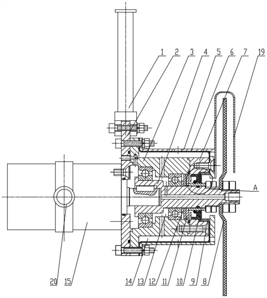
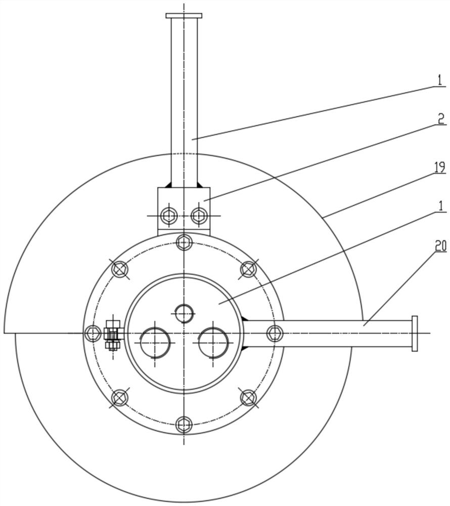
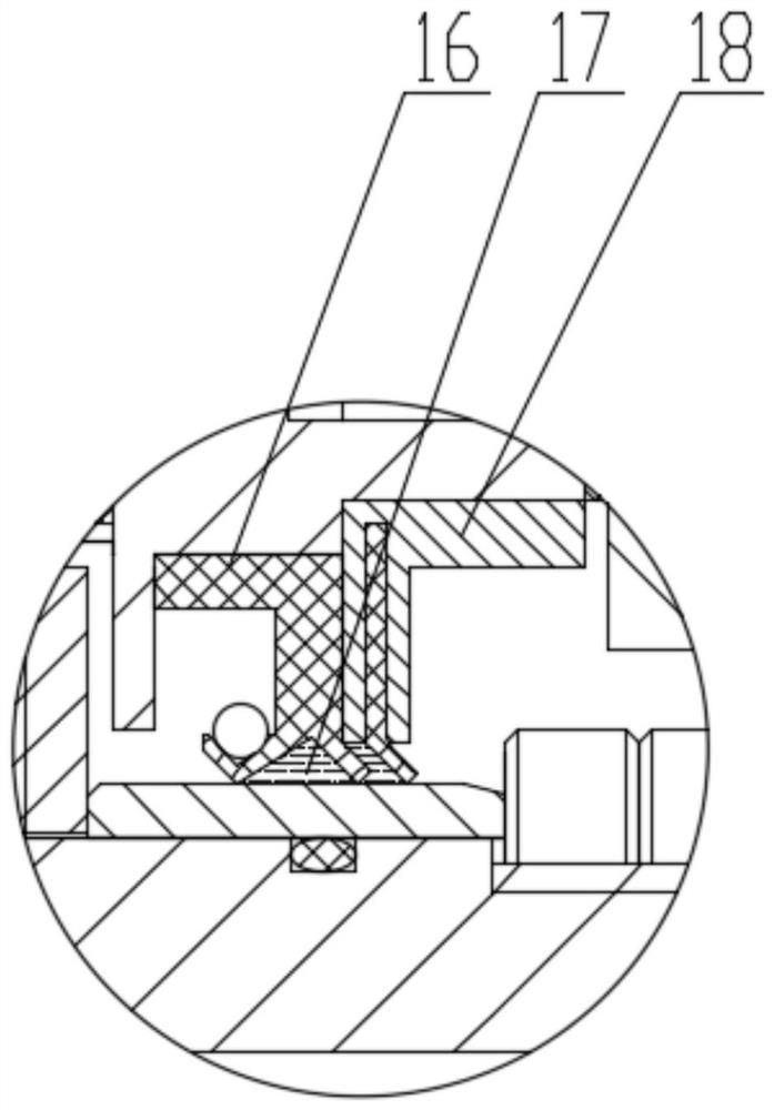
[0025] The specific implementation manner of the present invention will be described below in conjunction with the accompanying drawings.

[0026] Such as figure 1 , figure 2 and image 3 As shown, the pressure-adaptive high-speed light-duty underwater cutting tool of this embodiment includes a power element 15, and an output shaft 4 is installed through a key at the outlet of the power element 15. The output shaft 4 is stepped, and the first step surface and the The outer circumferential surface of the second stepped surface is equipped with a bearing chamber housing 3 through deep groove ball bearings, and one end of the bearing chamber housing 3 is installed with a flange 2 through a fastener, and a first handle is installed on the upper part of the flange 2 1. The flange 2 is locked with the power element 15 at the same time; a gasket 12 and a pair of disc springs 11 are installed outside the deep groove ball bearing on the second step surface, and a sleeve is installed...


PUM


Abstract

A pressure-adaptive high-speed light underwater cutting tool, including a power element, the output shaft of which is stepped, and bearing chamber shells are installed on the outer circumferential surfaces of the first stepped surface and the second stepped surface through deep groove ball bearings One end of the housing of the bearing cavity is equipped with a flange through a fastener, and the first handle is installed on the upper part of the flange, and the flange is locked with the power element at the same time; the outer part of the deep groove ball bearing on the second step surface is installed with a A gasket and a pair of disc springs, a sleeve is installed on the second stepped surface outside the disc spring, and a shaft seal assembly is installed on the outside of the sleeve; the outer end surface of the bearing chamber housing is equipped with an end cover through a seal, and the bearing chamber housing A compensation film protection cover is installed at a distance from the outer ring of the end cover at the same time, and a rubber compensation film is installed on the inner wall of the compensation film protection cover, which works reliably and is convenient for divers to work underwater.

Description

technical field [0001] The invention relates to the technical field of auxiliary equipment for diving operations, in particular to a pressure-adaptive high-speed light-duty underwater cutting tool. Background technique [0002] At present, most cutting tools on the market cannot be directly used by divers underwater. In addition to conventional sealing, material corrosion resistance and structural strength, there are also problems such as heavy weight and inability to adapt to high speed. In order to adapt to the water pressure at a large depth, the casing of the cutting tool is usually designed as a pressure-resistant structure or an external oil compensator is added, which will lead to excessive weight of the tool or complex system, which is not convenient for divers to operate. When the internal oil filling compensation of the cutting tool, the sealing problem of the external medium water and the internal compensation oil must be considered at the same time. Underwater to...

Claims


Application Information

Patent Timeline
Patent Type & Authority Patents(China)
IPC IPC(8): B23D79/00
CPCB23D79/00
Inventor 古浪韦正军陈志达王璇
Owner CHINA SHIP SCIENTIFIC RESEARCH CENTER (THE 702 INSTITUTE OF CHINA SHIPBUILDING INDUSTRY CORPORATION)
Why Eureka
Try Eureka