Hydraulic winch for underwater lifting of ship crane

A technology of hydraulic winches and ship cranes, which is applied in the field of hydraulic winches, and can solve the problems of incoordination between the speed ratio of the drum and the rope arrangement device, the increase of the accident rate of wire rope breaking, the staggering of wire ropes and the separation of seams, etc., so as to reduce slippage and improve Safety, damage reduction effect

Inactive Publication Date: 2020-12-25
广州联优科技有限公司
View PDF0 Cites 2 Cited by
  • Summary
  • Abstract
  • Description
  • Claims
  • Application Information

AI Technical Summary

Problems solved by technology

[0004] Aiming at the deficiencies of the prior art, the present invention provides a hydraulic winch for underwater hoisting of ship cranes, which has the advantages of good cable arrangement effect, avoids the staggered and separated seam phenomenon of steel wire ropes on the drum, and solves the problem of drum and rope arrangement. The speed ratio of the device is not coordinated, which makes it difficult for the steel wire rope to be wound in an orderly manner on the drum, resulting in the phenomenon of wire rope staggered and seam separation, which increases the accident rate of wire rope breakage and has a negative impact on the ship crane.

Method used


Image

  • Hydraulic winch for underwater lifting of ship crane
  • Hydraulic winch for underwater lifting of ship crane
  • Hydraulic winch for underwater lifting of ship crane

Examples


Embodiment Construction

[0032] The following will clearly and completely describe the technical solutions in the embodiments of the present invention with reference to the accompanying drawings in the embodiments of the present invention. Obviously, the described embodiments are only some, not all, embodiments of the present invention. Based on the embodiments of the present invention, all other embodiments obtained by persons of ordinary skill in the art without making creative efforts belong to the protection scope of the present invention.

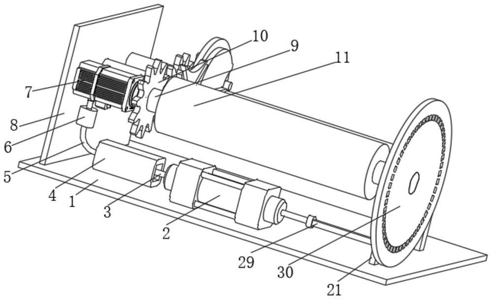
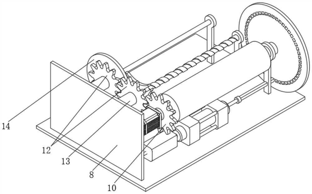
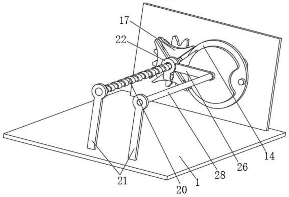
[0033] see Figure 1-6 , the present invention provides a technical solution: a hydraulic winch for underwater lifting of a ship crane, comprising a base 1, the left side of the top of the base 1 is fixedly connected to the bottom of the two-way hydraulic cylinder 2, and the left output end of the two-way hydraulic cylinder 2 is connected to the bottom of the two-way hydraulic cylinder 2. The right end of the push rod 3 is fixedly connected, the left end of th...


PUM


Abstract

The invention relates to the technical field of hydraulic winches, and discloses a hydraulic winch for underwater lifting of a ship crane. The hydraulic winch comprises a base, wherein the left side of the top of the base is fixedly connected with the bottom of a bidirectional hydraulic cylinder, the output end of the left side of the bidirectional hydraulic cylinder is fixedly connected with theright end of a push rod, the left end of the push rod is fixedly connected with the middle of a piston plate, and the outer side wall of the piston plate is slidably connected with the inner wall of an oil cylinder. According to the hydraulic winch for underwater lifting of the ship crane, the output end of a hydraulic motor drives a driving gear to rotate while driving a rotating shaft and a winding shaft to rotate, and the driving gear is matched with two sets of driven gears, so that a rotating disc drives a shifting rod to shift a stepping seat to rotate by 90 degrees in the rotating process; and through the guiding effect of a sliding rod on a sliding groove and the threaded fit of a lead screw and a screw seat, the screw seat moves by one fourth of the screw pitch length every time,the arrangement direction of steel wires is conveniently controlled, and the situation that the steel wires are staggered and separated when wound on the winding shaft is avoided.

Description

technical field [0001] The invention relates to the technical field of hydraulic winches, in particular to a hydraulic winch for underwater lifting of a ship crane. Background technique [0002] The winches can be divided into four types according to their usage methods: manual winches, electric winches, pneumatic winches, and hydraulic winches. At present, the largest domestic marine hydraulic winch is 350T, and the self-weight of the equipment reaches 150T. As a light and small lifting device that uses drums to wind steel wire ropes to lift heavy objects, hydraulic winches are widely used in the ship crane process. The working principle of the hydraulic winch is to use the oil as the working medium, to transmit the movement through the change of the sealed volume, and to transmit the power through the pressure inside the oil. At present, most of the hydraulic winches commonly used in my country are the JKY type developed in the 1980s. The hydraulic winch or the winch impro...

Claims


Application Information

Patent Timeline
Patent Type & Authority Applications(China)
IPC IPC(8): B66D1/08B66D1/14B66D1/28B66D1/36
CPCB66D1/08B66D1/14B66D1/28B66D1/36
Inventor 李云娜
Owner 广州联优科技有限公司
Why Eureka
Try Eureka