Hub-driven planetary worm speed reducer assembly

A technology of planetary worm and wheel hub drive, which is applied in transmission boxes, electric components, transmission parts, etc., can solve the problems of difficult industrial application, high production cost, and large space occupation, and achieve the solution of many parts, compact structure, and simplified effect

Inactive Publication Date: 2020-12-25
FUZHOU UNIV
View PDF2 Cites 0 Cited by
  • Summary
  • Abstract
  • Description
  • Claims
  • Application Information

AI Technical Summary

Problems solved by technology

However, at present, the hub motor deceleration drive structure takes up a lot of space, high production cost, and relatively low efficiency, making it difficult to realize batch industrial application

Method used


Image

  • Hub-driven planetary worm speed reducer assembly
  • Hub-driven planetary worm speed reducer assembly
  • Hub-driven planetary worm speed reducer assembly

Examples


Embodiment Construction

[0018] The present invention will be described in further detail below in conjunction with the accompanying drawings and specific embodiments.

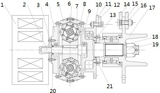
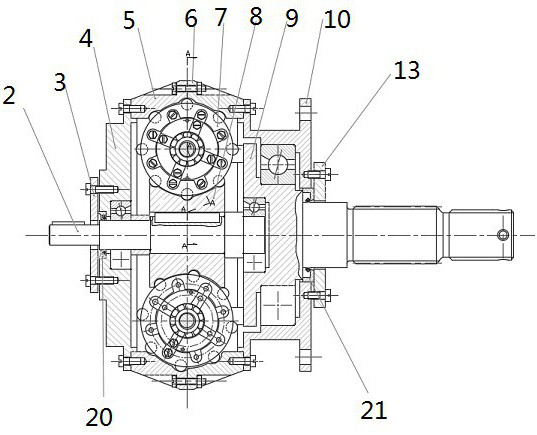
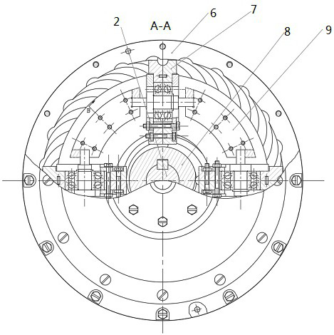
[0019] Example: such as Figure 1~3 As shown, a hub-driven planetary worm reducer assembly is provided, including a drive mechanism, a reduction mechanism and a hub mechanism arranged from left to right. The reduction mechanism includes a reduction input shaft 2, and a center is provided in the middle of the reduction input shaft. Worm wheel 8, said center worm wheel has 4 planetary worm gears 7 meshed with the center worm wheel evenly distributed along the center worm wheel circumferential direction, and each planetary worm wheel is provided with the first inner gear 5 and the first inner gear 5 meshed with the planetary worm wheel away from the center worm wheel The second internal gear 6 is coaxially provided with a planetary carrier mechanism 9 on the right side of the reduction input shaft, and the right side of the planetary car...


PUM


Abstract

The invention provides a hub-driven planetary worm speed reducer assembly. The hub-driven planetary worm speed reducer assembly comprises a driving mechanism, a speed reducing mechanism and a hub mechanism which are arranged from left to right. The speed reducing mechanism comprises a speed reducing input shaft, and a center worm wheel is arranged in the middle of the speed reducing input shaft. Four planetary worm wheels engaged with the center worm wheel are evenly distributed on the center worm wheel in the circumferential direction of the center worm wheel. A first inner gear and a secondinner gear engaged with the planetary worm wheels are arranged on the sides, away from the center worm wheel, of the planetary worm wheels, and a planet carrier mechanism is coaxially arranged on theright side of the speed reducing input shaft. The right side of the planet carrier mechanism is connected with the hub mechanism, and power output by the driving mechanism is directly output to wheelsthrough the speed reducing mechanism. The hub-driven planetary worm speed reducer assembly is reasonable in design, compact in structure and high in efficiency, the weight is greatly lowered while transmission power is greatly improved, materials are saved and cost is reduced.

Description

technical field [0001] The invention relates to a hub-driven planetary worm reducer assembly. Background technique [0002] In recent years, electric vehicle technology has been developing continuously, and electric wheel drive, as a new electric vehicle drive technology, has become the development direction of the next generation of vehicles. There are three main configurations of electric wheels: hub motor direct drive configuration, hub motor deceleration drive configuration and wheel side motor deceleration drive configuration. Compared with the other two configurations, it can be found that the in-wheel motor deceleration drive mode has significant competitiveness and advantages in terms of structural layout, transmission efficiency, power performance and energy management. However, at present, the hub motor deceleration drive structure takes up a lot of space, has high production costs, and relatively low efficiency, making it difficult to achieve mass industrial appl...

Claims


Application Information

Patent Timeline
Patent Type & Authority Applications(China)
IPC IPC(8): F16H57/02F16H57/021F16H57/023F16H57/039F16H57/08H02K7/116
CPCF16H57/02F16H57/021F16H57/023F16H57/039F16H57/08F16H2057/02034F16H2057/02043F16H2057/02086F16H2057/02091H02K7/116
Inventor 姚立纲陈欣欣曾雪莲王亚丽潘成
Owner FUZHOU UNIV
Why Eureka
Try Eureka