Self-driving vehicle test system and aebs, fcws test method

A technology of automatic driving and testing system, which is applied in the direction of vehicle testing, machine/structural component testing, measuring devices, etc., and can solve the unfavorable AEBS and FCWS test evaluation methods of autonomous driving vehicles, which are not suitable for batch testing applications of automatic driving vehicles, Problems such as the performance testing environment cannot be integrated to achieve the effect of low test cost, easy promotion, and reasonable evaluation

Active Publication Date: 2022-05-10
SHANDONG ACAD OF SCI INST OF AUTOMATION +1
View PDF10 Cites 0 Cited by
  • Summary
  • Abstract
  • Description
  • Claims
  • Application Information

AI Technical Summary

Problems solved by technology

However, at present, domestic and foreign tests of AEBS and FCWS of autonomous vehicles are mainly carried out outdoors according to actual traffic scenarios. During the test, traffic management is required on the test road section, and the site requirements are relatively strict, so the cost is high and it is not suitable for automatic driving. Batch test application for driving vehicles; it cannot be integrated into the existing conventional vehicle performance testing environment; it is not conducive to the formation of objective test and evaluation methods for AEBS and FCWS of autonomous vehicles

Method used


Image

  • Self-driving vehicle test system and aebs, fcws test method
  • Self-driving vehicle test system and aebs, fcws test method
  • Self-driving vehicle test system and aebs, fcws test method

Examples


Embodiment 1

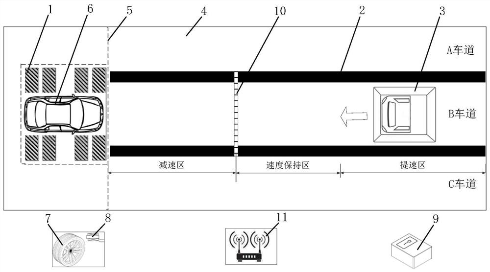
[0089] Such as figure 1 As shown, a self-driving vehicle test system includes a test site 4, a dynamometer 1, a vehicle under test 6, a communication device 11 and a console 9, and also includes a test background vehicle 3 and an induction magnetic strip 10. The test site 4 is marked with a lane line 2 and three lanes of A, B, and C are established, and the test site 4 is divided into a speed-up area, a speed-maintaining area, and a deceleration area perpendicular to the lane line 2; The induction magnetic strip 10 that is arranged on the B track between the speed maintenance areas is movable; the test background car 3 is located at one end of the test site 4, and is located in the A, B, and C lanes, and the test background car 3 is provided with an induction magnetic strip. The magnetic signal receiver of bar 10; the four-wheel output of the vehicle under test 6 is connected to the dynamometer 1, the vehicle under test 6 is located on the dynamometer 1, and is located at the ...

Embodiment 2

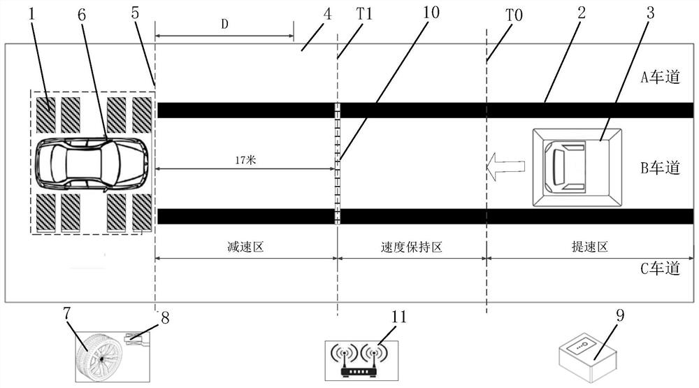
[0095] Such as figure 2 As shown, a schematic diagram of a self-driving vehicle AEBS longitudinal movement state performance test system, the test system includes a dynamometer 1, a test background car 3, a tire speed sensor 8 for measuring the speed of the vehicle tire 7 under test, a communication device 11, an induction The magnetic strip 10 is a magnetic signal receiver for receiving the signal of the induction magnetic strip 10, and the test background vehicle 3 is placed in the B lane. The test here simplifies the scene where the vehicle under test 6 drives towards the background vehicle at a certain speed under normal road conditions, and abstracts the vehicle under test 6 to stand still, but uses the dynamometer 1 to keep the vehicle under test 6 at the speed required for the test. In the mechanical state, the test background vehicle 3 moves towards the tested vehicle 6, thereby simulating the scene where the distance between the two vehicles is continuously shortened...

Embodiment 3

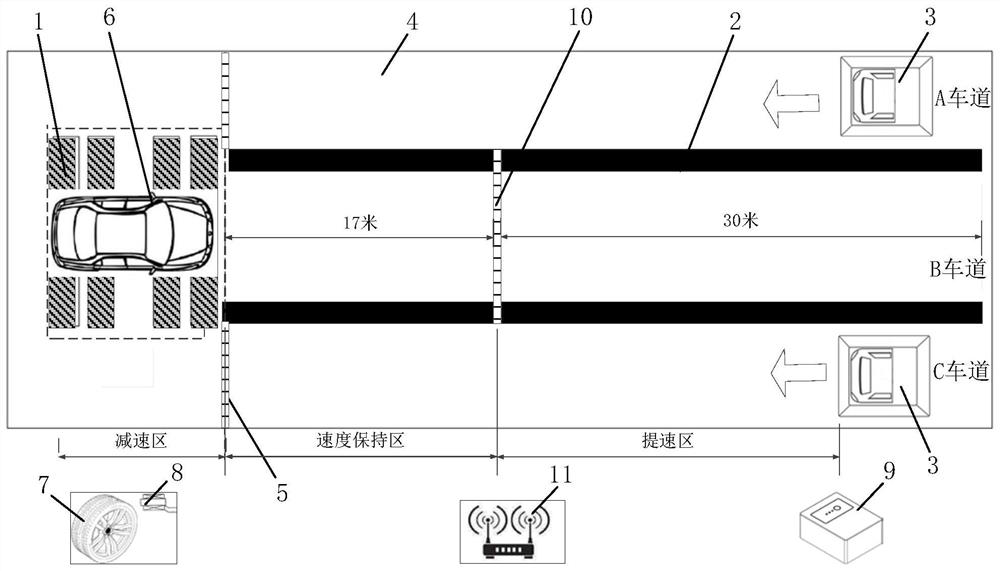
[0117] Such as image 3 As shown, a schematic diagram of an autonomous vehicle AEBS false response test system. Among them, the equipment involved includes: a dynamometer 1, a vehicle under test 6, two test background vehicles 3, a tire speed sensor 8 for measuring the rotation speed of the tire 7 of the vehicle under test, and a tire speed sensor 8 for controlling the vehicle under test 6 and the test background vehicle. 3 The console 9, the communication device 11, the induction magnetic strip 10 and the vehicle-mounted magnetic signal receiver etc. of the corresponding speed.

[0118] combine Figure 5 Understanding a false response test and evaluation method for AEBS of autonomous vehicles, including the following steps:

[0119] Step (S2100) Before the test starts, system initialization and self-testing of various equipment should be carried out. The two test background cars 3 are respectively located at the other end of the two adjacent lanes of the tested vehicle 6, a...


PUM


Abstract

The invention discloses a self-driving vehicle test system, which includes a test site, a dynamometer, a vehicle under test, communication equipment, a console and a test background vehicle. The test site is provided with three lanes A, B and C, vertically An induction magnetic strip is provided on the lane line; the test background vehicle and the vehicle under test are respectively located at both ends of the test site, a magnetic signal receiver is provided on the background vehicle, and the four-wheel output of the vehicle under test is connected to the dynamometer and passed through the fixture fixed, the console is communicatively connected to the dynamometer, the vehicle under test and the test background car through the communication device, the console controls the vehicle under test, the dynamometer and the test background car through the communication device, and monitors their status and vehicle speed, Therefore, the test system occupies a small space and has low cost; AEBS and FCWS test methods suitable for the tested vehicle are also disclosed, and the method standardizes the test procedure for emergency braking of the vehicle, making the test evaluation more reasonable and effective.

Description

technical field [0001] The invention relates to the field of automatic driving vehicle testing systems, in particular to an automatic driving vehicle testing system and AEBS and FCWS testing methods that can be implemented in a limited space. Background technique [0002] Explanation of terms: [0003] AEBS: Automatic Emergency Braking System [0004] FCWS: Forward Collision Warning System [0005] Autonomous driving technology is divided into multiple levels. At present, domestic and foreign industries adopt more classification standards introduced by the Society of Automotive Engineers (SAE) and the National Highway Safety Administration (NHTSA). According to the SAE standard, the level of intelligence and automation of self-driving cars is divided into six levels: no automation-L0, driving support-L1, partial automation-L2, conditional automation-L3, high degree of automation-L4 and full automation-L5 . [0006] At this stage, the research on autonomous driving at hom...

Claims


Application Information

Patent Timeline
Patent Type & Authority Patents(China)
IPC IPC(8): G01M17/007
CPCG01M17/007
Inventor 李研强陈泓运张子辉车晓波李超王康
Owner SHANDONG ACAD OF SCI INST OF AUTOMATION
Why Eureka
Try Eureka