Ultrasonic wave range setting method and system

An ultrasonic and range technology, applied in the control/regulation system, non-electric variable control, two-dimensional position/channel control and other directions, can solve the problem that the robot cannot immediately know the exact position of the obstacle, affects the robot's motion efficiency, and the robot is dangerous. , to reduce the risk of collision, increase the safety factor, and avoid the effect of collision

Pending Publication Date: 2020-12-25
上海木木聚枞机器人科技有限公司
View PDF6 Cites 0 Cited by
  • Summary
  • Abstract
  • Description
  • Claims
  • Application Information

AI Technical Summary

Problems solved by technology

Therefore, once an obstacle is measured, the robot cannot immediately know the exact position of the obstacle, but only knows that within a certain angle range, there is an obstacle at this distance
When the robot is moving fast, a larger detection distance can be safer, but if it detects objects on the wall, it may cause the robot to think that there are obstacles ahead, which will slow down and affect the robot's movement efficiency; if the detection distance is small, the distance from glass and other Obstacles that are too close to be detected are too dangerous for the robot

Method used


Image

  • Ultrasonic wave range setting method and system
  • Ultrasonic wave range setting method and system
  • Ultrasonic wave range setting method and system

Examples


Embodiment 1

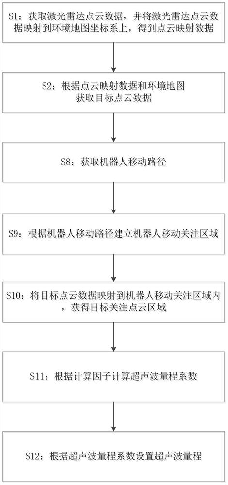
[0057] Such as figure 1 As shown, the present embodiment provides a method for setting the ultrasonic range, including:

[0058] S1: Obtain the lidar point cloud data of the robot's current working environment, and map the lidar point cloud data to the environment map coordinate system to obtain point cloud mapping data;

[0059] S2: Obtain target point cloud data according to the point cloud mapping data and the environment map; the target point cloud data is in a blank area in the environment map and the distance from the fixed obstacle in the environment map is not less than the preset point cloud point cloud of distance;

[0060] S8: Obtain the robot movement path planning of the robot;

[0061] S9: Establishing a robot movement focus area according to the robot movement path planning;

[0062] S10: Map the target point cloud data to the robot movement focus area to obtain the target focus point cloud area;

[0063] S11: Calculate the ultrasonic range coefficient accor...

Embodiment 2

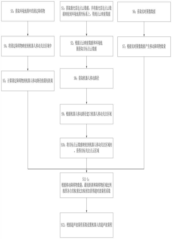
[0068] Such as figure 2 As shown, the present embodiment provides a method for setting the ultrasonic range, and the present embodiment includes:

[0069] S1: Obtain the lidar point cloud data of the robot's current working environment, and map the lidar point cloud data to the environment map coordinate system to obtain point cloud mapping data;

[0070] S2: Obtain target point cloud data according to the point cloud mapping data and the environment map; the target point cloud data is in a blank area in the environment map and the distance from the fixed obstacle in the environment map is not less than a preset point point cloud of cloud distance;

[0071] S3: Acquiring fixed obstacles in the environment map;

[0072] S4: Map the fixed obstacle to the mobile attention area of ​​the robot;

[0073] S5: Calculating the shortest distance from the fixed obstacle to the planned moving path of the robot;

[0074] S6: The calculation factor also includes the number of moving ob...

Embodiment 3

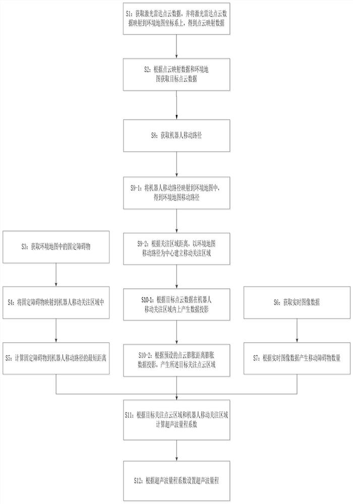
[0085] Such as image 3 As shown, the present embodiment provides a method for setting the ultrasonic range, and the present embodiment includes:

[0086] S1: Obtain the lidar point cloud data of the robot's current working environment, and map the lidar point cloud data to the environment map coordinate system to obtain point cloud mapping data;

[0087] S2: Obtain target point cloud data according to the point cloud mapping data and the environment map; the target point cloud data is in a blank area in the environment map and the distance from the fixed obstacle in the environment map is not less than the preset point cloud point cloud of distance;

[0088] S3: Acquiring fixed obstacles in the environment map;

[0089] S4: Map the fixed obstacle to the mobile attention area of ​​the robot;

[0090] S5: Calculating the shortest distance from the fixed obstacle to the planned moving path of the robot;

[0091] S6: Obtain real-time image data through the camera;

[0092] S...


PUM


Abstract

The invention discloses an ultrasonic wave range setting method. The method comprises the steps that laser radar point cloud data of the current working environment of a robot is acquired, and the laser radar point cloud data is mapped to an environment map coordinate system to obtain point cloud mapping data; target point cloud data is acquired according to the point cloud mapping data and an environment map; a robot moving path plan of the robot is acquired; a robot moving attention area is established according to the robot moving path plan; the target point cloud data is mapped into the robot moving attention area to obtain a target attention point cloud area; an ultrasonic wave range coefficient is calculated according to the target attention point cloud area and the robot moving attention area; and the ultrasonic wave range of the robot is set according to the ultrasonic wave range coefficient. The invention furthermore discloses an ultrasonic wave range setting system. Accordingto the method and system, the ultrasonic wave range is dynamically set through the laser radar point cloud data, on one hand, the safety coefficient is increased, and on the other hand, the situationthat the movement efficiency is influenced due to the fact that the measurement distance is too large is avoided.

Description

technical field [0001] The invention relates to ultrasonic positioning, in particular to an ultrasonic range setting method and system. Background technique [0002] Ultrasonic sensors are sensors that are often used by robots. It is not affected by light, dust, etc., and can detect things that cannot be detected by distance sensors that use light characteristics as a detection method, such as transparent glass; but due to the characteristics of sound waves, the detection angle of ultrasonic sensors is relatively large, often within ten A few degrees, even tens of degrees. Therefore, once the obstacle is measured, the robot cannot immediately know the exact position of the obstacle, but can only know that there is an obstacle at this distance within a certain angle range. When the robot is moving fast, a larger detection distance can be safer, but if it detects objects on the wall, it may cause the robot to think that there are obstacles ahead, which will slow down and aff...

Claims


Application Information

Patent Timeline
Patent Type & Authority Applications(China)
IPC IPC(8): G05D1/02
CPCG05D1/024G05D1/0246G05D1/0255G05D1/0257G05D1/0214G05D1/0276
Inventor 张干
Owner 上海木木聚枞机器人科技有限公司
Why Eureka
Try Eureka