Stator, motor, compressor and refrigeration equipment
A stator and stator slot technology, used in the fields of stators, motors, compressors and refrigeration equipment, can solve the problems of motor demagnetization, frequent maintenance, affecting the normal use of motors, etc. Effect
- Summary
- Abstract
- Description
- Claims
- Application Information
AI Technical Summary
Problems solved by technology
Method used
Image
Examples
Embodiment 1
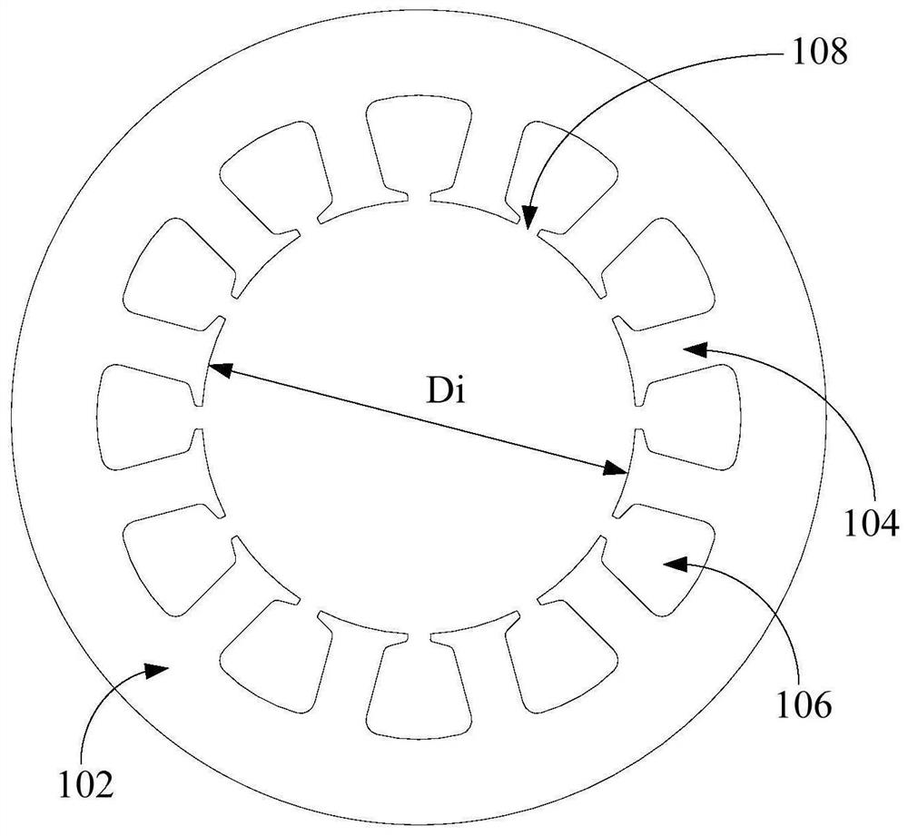
[0046] Such as figure 1 and figure 2 As shown, the first embodiment of the present invention proposes a stator, including: a stator core 102 .
[0047] Wherein, the stator core 102 includes a plurality of stator teeth 104 , and the plurality of stator teeth 104 are distributed along the circumference of the stator core 102 and extend toward the axis of the stator core 102 . Wherein, a stator slot 106 is formed between two adjacent stator teeth 104 , the stator slot 106 has a notch 108 , and the notch 108 is located at one end facing the axial center of the stator core 102 .
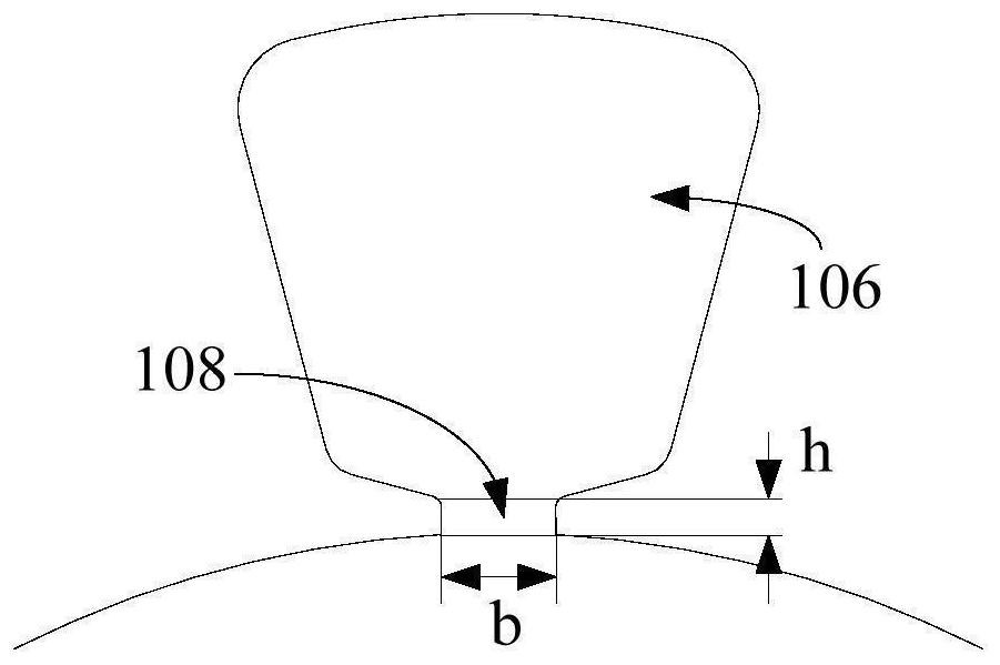
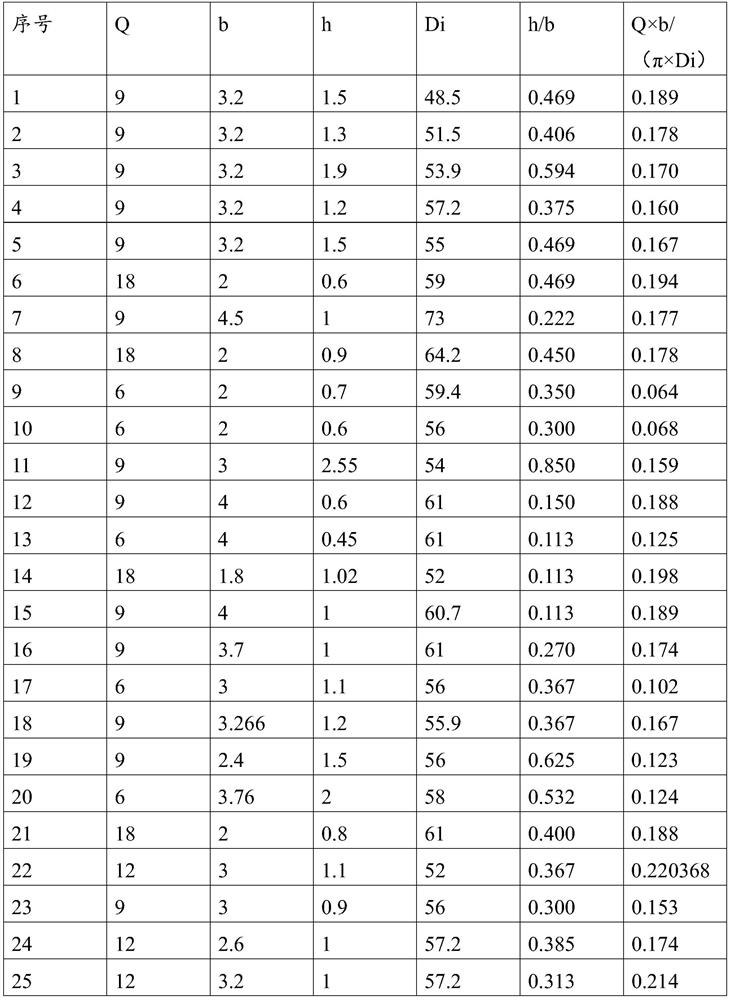
[0048] Such as figure 2 As shown, the width of the notch 108 is b, the height of the notch 108 along the radial direction of the stator core 102 is h, and satisfy 0.31≤h / b≤0.39. That is, the ratio of the height h to the width b of the notch 108 must be greater than or equal to 0.31 and less than or equal to 0.39.
[0049] It should be noted that the width and height of the slots 108 of the stator core...
Embodiment 2
[0053] Such as figure 1 and figure 2 As shown, the second embodiment of the present invention proposes a stator, including: a stator core 102 .
[0054] Wherein, the stator core 102 includes a plurality of stator teeth 104 , and the plurality of stator teeth 104 are distributed along the circumference of the stator core 102 and extend toward the axis of the stator core 102 . Wherein, a stator slot 106 is formed between two adjacent stator teeth 104 , the stator slot 106 has a notch 108 , and the notch 108 is located at one end facing the axial center of the stator core 102 .
[0055] Such as figure 2 As shown, the width of the notch 108 is b, the height of the notch 108 along the radial direction of the stator core 102 is h, the inner diameter of the stator core 102 is Di, the number of stator slots 106 is Q, and 0.17≤Q× b / (π×Di)≦0.22.
[0056] It is worth noting that the stator slot 106 is a semi-open slot, slot opening will lead to an increase in air gap harmonics, whi...
Embodiment 3
[0058] Such as figure 1 and figure 2 As shown, the third embodiment of the present invention proposes a stator, including: a stator core 102 .
[0059] Wherein, the stator core 102 includes a plurality of stator teeth 104 , and the plurality of stator teeth 104 are distributed along the circumference of the stator core 102 and extend toward the axis of the stator core 102 . Wherein, a stator slot 106 is formed between two adjacent stator teeth 104 , the stator slot 106 has a notch 108 , and the notch 108 is located at one end facing the axial center of the stator core 102 .
[0060] Such as figure 2 As shown, the width of the notch 108 is b, the height of the notch 108 along the radial direction of the stator core 102 is h, and satisfy 0.31≤h / b≤0.39. That is, the ratio of the height h of the notch 108 to the width b is greater than or equal to 0.31 and less than or equal to 0.39.
[0061] Further, the inner diameter of the stator core 102 is Di, the number of the stator ...
PUM
 Abstract
Description
Claims
Application Information
 - R&D
- Intellectual Property
- Life Sciences
- Materials
- Tech Scout
- Unparalleled Data Quality
- Higher Quality Content
- 60% Fewer Hallucinations
Browse by: Latest US Patents, China's latest patents, Technical Efficacy Thesaurus, Application Domain, Technology Topic, Popular Technical Reports.
© 2025 PatSnap. All rights reserved.Legal|Privacy policy|Modern Slavery Act Transparency Statement|Sitemap|About US| Contact US: help@patsnap.com


