Demagnetization device and method for telescopic guide sleeve of hub bearing

A wheel hub bearing, telescopic technology, applied in the direction of magnetic objects, electrical components, circuits, etc., can solve the problems of insufficient demagnetization of bearing inner ring parts, reduced bearing service life, unsmooth bearing operation, etc., to achieve enhanced demagnetization effect, adaptability Strong, solve the effect of insufficient surface demagnetization

Active Publication Date: 2017-07-28
WUHAN HUAYUYIMU TESTING EQUIP CO LTD
View PDF5 Cites 1 Cited by
  • Summary
  • Abstract
  • Description
  • Claims
  • Application Information

AI Technical Summary

Problems solved by technology

During the operation of the bearing, iron powder will be produced by the friction between the ball and the groove. Due to the large residual magnetism, the bearing parts will also absorb the iron powder, resulting in the unsmooth operation of the bearing and reducing the service life of the bearing.
Bearing parts must be demagnetized before they can enter the assembly process. Since the outer ring parts of the bearing form a magnetic shield for the inner ring parts, it is difficult for the magnetic field lines to enter the inner ring parts of the bearing by the conventional AC demagnetization method, which makes it difficult to demagnetize the bearing as a whole. In order to avoid the bearing being magnetized At this stage, no magnetic technology is used in the hub bearing assembly process
The end face of the hub bearing is a complex curved surface, the magnetic force lines of the conventional AC demagnetization method are shielded by the outer ring parts, the demagnetization of the inner ring parts of the bearing is insufficient, the residual magnetism is uneven, and the residual magnetism in some places is easy to exceed the standard

Method used


Image

  • Demagnetization device and method for telescopic guide sleeve of hub bearing
  • Demagnetization device and method for telescopic guide sleeve of hub bearing
  • Demagnetization device and method for telescopic guide sleeve of hub bearing

Examples


Embodiment Construction

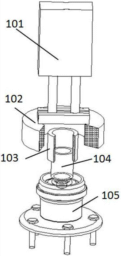
[0027] The principles and features of the present invention are described below in conjunction with the accompanying drawings, and the examples given are only used to explain the present invention, and are not intended to limit the scope of the present invention. In order to simplify the model, the following description uses a two-stage magnetic guide sleeve structure to introduce the present invention in detail, and the actual application process is not limited to the two-stage magnetic guide sleeve structure.

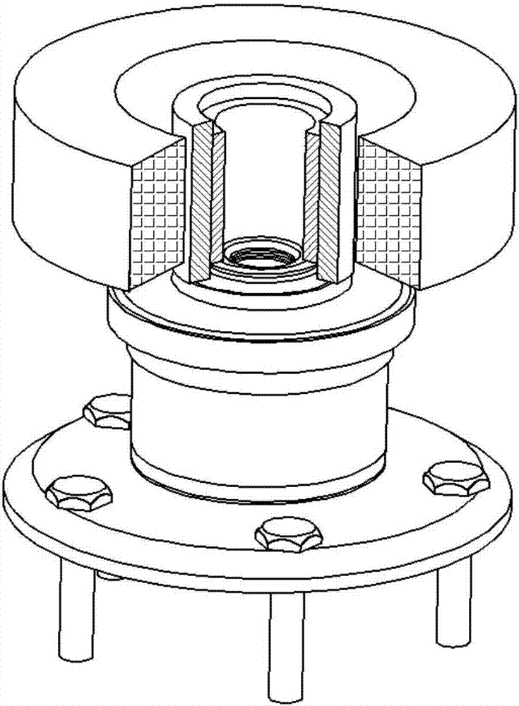
[0028] Such as figure 1 Shown is the wheel bearing telescopic guide sleeve demagnetization device of the present invention, which mainly includes a rod cylinder 101, an AC demagnetization coil 102, a telescopic magnetic guide sleeve and a hub bearing 105, and the piston rod of the rod cylinder 101 is connected to the The upper end surface of the AC demagnetization coil 102 is fixedly connected, and can drive the AC demagnetization coil 102 to move up and down. The tel...


PUM


Abstract

The invention belongs to a demagnetizing technology, in particular to a telescopic guide sleeve demagnetizing device and method of a wheel hub bearing. The device comprises an AC demagnetizing coil, a telescopic magnetic guide sleeve and a drawbar air cylinder, wherein the magnetic guide sleeve is arranged at the center of the AC demagnetizing coil. Through step-by-step lamination of a telescopic structure and a spinning surface of the wheel hub bearing, a complex surface is changed into a regular magnetic conductor; the magnetic guide sleeve is separated step by step when separated; and asynchronous attenuation of a magnetic field at the inner ring end surface of the wheel hub bearing is controlled, so that uniform demagnetization of inner ring parts of the wheel hub bearing is achieved. By an AC demagnetizing method, the magnetic field acts on the inner ring parts of the wheel hub bearing through cooperation with the telescopic guide sleeve; and the telescopic guide sleeve demagnetizing device and method are especially suitable for demagnetization of complex curved parts, in an inner cavity of an assembly body, similar to the spinning surface of the wheel hub bearing, and have the characteristics of high efficiency, high space adaptability and the like.

Description

technical field [0001] The invention belongs to the demagnetization technology, and is a demagnetization device and method for a telescopic guide sleeve of a wheel hub bearing, which is especially suitable for the demagnetization of the spinning surface of the wheel hub bearing, and is also suitable for the demagnetization of complex curved surface parts and space curved surface parts in the assembly cavity, and is a high-efficiency , Low energy demagnetization method. Background technique [0002] The third-generation wheel hub bearings use the spinning process to assemble the inner and outer ring parts of the bearing. During the spinning process, the metal is deformed, and the residual stress easily leads to excessive residual magnetism; the eddy current and magnetic flux leakage method is used to detect the residual magnetism of the inner ring of the bearing after the spinning surface of the wheel hub bearing. Higher magnetic. During the operation of the bearing, the fri...

Claims


Application Information

Patent Timeline
Patent Type & Authority Patents(China)
IPC IPC(8): H01F13/00
CPCH01F13/006
Inventor 李二龙
Owner WUHAN HUAYUYIMU TESTING EQUIP CO LTD
Why Eureka
Try Eureka