Visual intraoperative stent delivery device and intraoperative stent system thereof

A delivery device and stent system technology, which is applied to stents, devices with human tubular structures, blood vessels, etc., can solve the problems of inability to see the distal implantation, transintimal breach into the false lumen, and dilation and rupture of the descending aorta To achieve the effect of improving surgical safety and surgical efficiency, reducing surgical cost, and reducing surgical risk

Active Publication Date: 2020-12-29
FUWAI HOSPITAL CHINESE ACAD OF MEDICAL SCI & PEKING UNION MEDICAL COLLEGE
View PDF10 Cites 0 Cited by
  • Summary
  • Abstract
  • Description
  • Claims
  • Application Information

AI Technical Summary

Problems solved by technology

[0004] The inventors of the present invention have found in long-term practice that the intraoperative stent system still has at least the following technical problems in clinical application: the introduction process of the covered stent through the delivery device is blind to a certain extent, because the operator can only see the chest descending clearly. The condition of the proximal end of the aorta cannot see the implantation of the distal end, so the operation often requires special guidance or judgment based on the experience of the surgeon; the former requires CT imaging data, or advances through the femoral artery under X-ray guidance The guide wire is then introduced into the elephant trunk stent through the guide wire, which needs to be completed in the hybrid operating room, which increases the complexity of the operation and is not conducive to popularization and application; lumen risk, which, if occurred, would have catastrophic consequences for continued dilation and rupture of the descending aorta

Method used


Image

  • Visual intraoperative stent delivery device and intraoperative stent system thereof
  • Visual intraoperative stent delivery device and intraoperative stent system thereof
  • Visual intraoperative stent delivery device and intraoperative stent system thereof

Examples


Embodiment 1

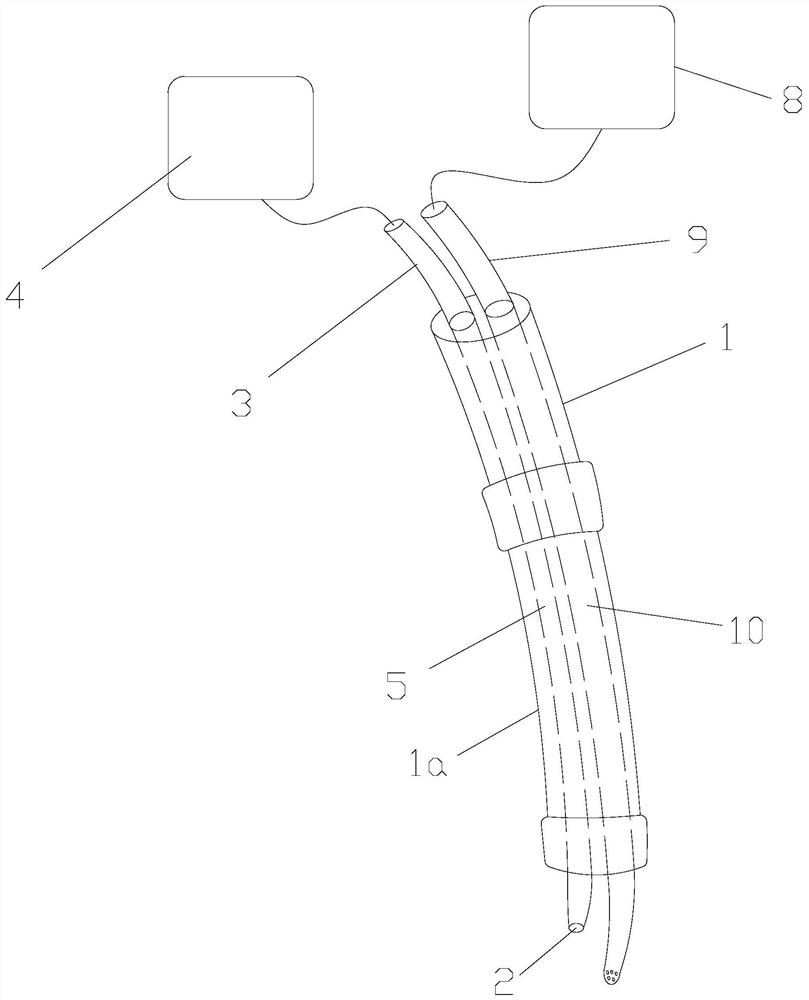
[0027]Such asfigure 1 As shown, this embodiment provides a visual intraoperative stent delivery device, which includes a support rod 1. The delivery device also includes a probe end 2 for real-time detection of image information connected in sequence, and a transmission for transmitting image signals. The tube 3 and the display end 4 for displaying images; the support rod 1 is provided with an image channel 5, the inlet end of the image channel 5 is located at the rear section of the support rod 1, and the outlet end is located at the front end surface of the support rod 1. The transmission tube 3 penetrates from the inlet end of the image channel 5 and exits from the outlet end of the image channel 5 and is connected to the probe end 2.

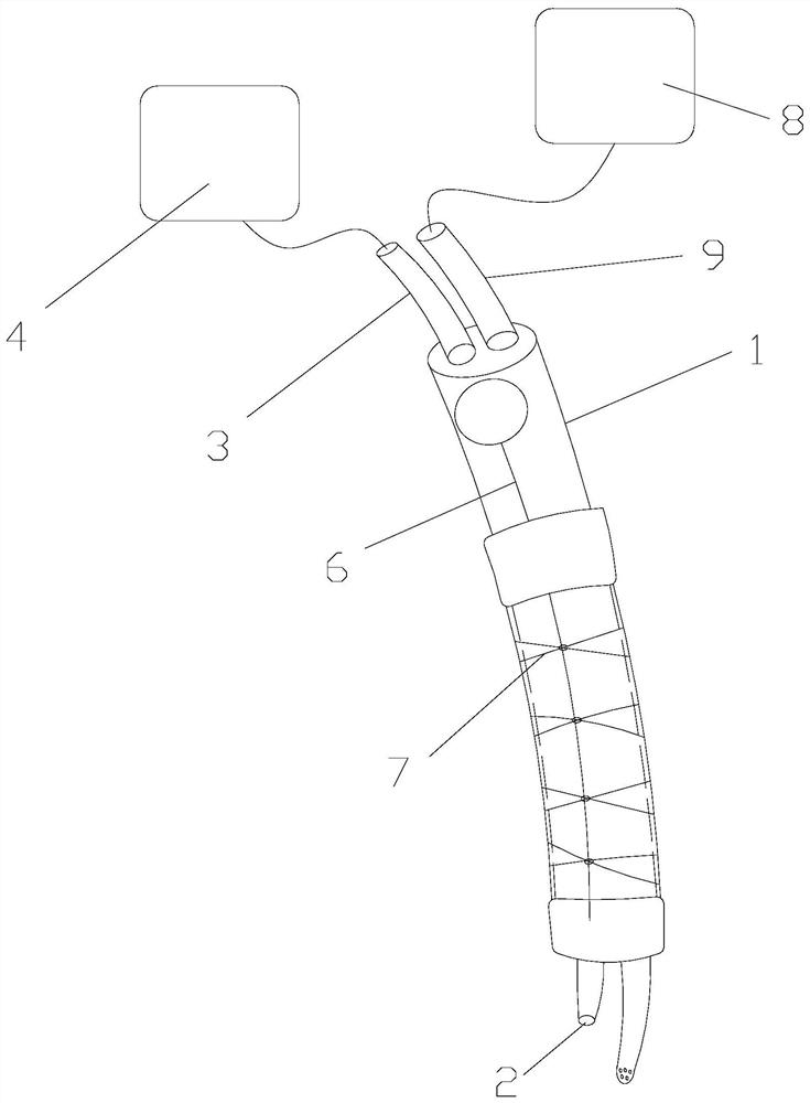
[0028]In addition to the support rod 1, the intraoperative stent delivery device also includes components such as a metal tie rod 6 and a lashing line 7, and its use is basically the same as the prior art. See patents CN 106618822 A and CN 104622600A...

Embodiment 2

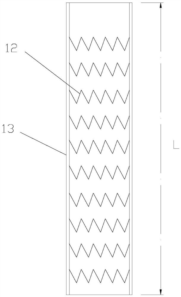
[0037]Such asFigure 1 to Figure 3Shown: this embodiment provides an intraoperative stent system, including a delivery device provided with a support rod 1 and a stent graft. The front section of the support rod 1 is provided with a mounting portion 1a for installing the stent graft; The stent graft includes a metal mesh 12 with a self-expanding structure and a covering film 13 covering the metal mesh 12. The metal mesh 12 is configured to be compressed on the mounting portion 1a by the covering film 13, and is released by releasing the covering film 13 The compressive force positions and releases the stent graft at the target position.

[0038]In addition to the support rod 1, the conveying device also includes a metal tie rod 6 and a lashing line 7, and its use is basically the same as the prior art. See patents CN 106618822 A and CN 104622600A. The support rod 1 may include a front section and a rear section. The front section is provided with a mounting portion 1a for installing the...


PUM


Abstract

The invention relates to the field of cardiovascular medical treatment, and particularly discloses a visual intraoperative stent delivery device and an intraoperative stent system thereof. The delivery device comprises a supporting rod, a probe end used for detecting image information in real time, a transmission tube used for image signal transmission and a displaying end used for displaying images, wherein the probe end, the transmission tube and the displaying end are connected in sequence; an image channel is arranged in the supporting rod; an entrance end of the image channel is located at the rear section of the supporting rod, and an exit end of the image channel is located on the front end face of the supporting rod; and the transmission tube penetrates from the entrance end of theimage channel and is connected with the probe end after penetrating out from the exit end of the image channel; the intraoperative stent system comprises the delivery device and a covered stent; thecovered stent includes a metal net of a self-expandable structure and a cover film coating the metal net; and the metal net is configured to be compressed on the supporting rod through the cover film.The visual intraoperative stent delivery device and the intraoperative stent system can realize distant end visualization of the covered stent implantation, thereby lowering the operation risk.

Description

Technical field[0001]The invention relates to the field of cardiovascular medical treatment, in particular to a visual type intraoperative stent delivery device and an intraoperative stent system including the visual type intraoperative stent delivery device.Background technique[0002]Aortic dissection is an acute aortic disease with rapid onset, rapid progress, high mortality, difficult surgery, and poor prognosis; the pathophysiology of aortic dissection is that the aortic intima ruptures and blood flow rushes into the middle aorta, leading to The middle layer of the aorta splits to form true and false cavities; at present, the most common surgical method for the treatment of aortic dissection and aortic aneurysms is aortic arch replacement and stent trunk surgery, which uses deep hypothermic circulatory arrest to replace artificial quadrant vessels. The aortic arch and its three vascular branches (brachial trunk, left common carotid artery, left subclavian artery), and simultaneou...

Claims


Application Information

Patent Timeline
Patent Type & Authority Applications(China)
IPC IPC(8): A61F2/07A61F2/95
CPCA61F2/07A61F2/95A61F2002/077
Inventor 郭宏伟畅怡方方魏柯范舒雅刘创
Owner FUWAI HOSPITAL CHINESE ACAD OF MEDICAL SCI & PEKING UNION MEDICAL COLLEGE
Why Eureka
Try Eureka