Steel bar hoop-bending machine for steel bar processing

A steel bar processing and hoop bending machine technology, applied in the field of steel bar bending hoops, can solve problems such as inaccurate bending of steel bars, and achieve the effect of promoting work efficiency and reducing surface temperature

Active Publication Date: 2020-12-29
冠县德汇商贸有限公司
View PDF24 Cites 1 Cited by
  • Summary
  • Abstract
  • Description
  • Claims
  • Application Information

AI Technical Summary

Problems solved by technology

[0004]Although the overall device has achieved the effect of bending hoops on steel bars, most of the bending hoops of steel bars are carried out at the construction site. The time is irradiated by the sun, resulting in high surface temperature of the steel bar and the workbench, and when the hoop bending equipment is working, it often causes the problem of inaccurate bending of the steel bar

Method used


Image

  • Steel bar hoop-bending machine for steel bar processing
  • Steel bar hoop-bending machine for steel bar processing
  • Steel bar hoop-bending machine for steel bar processing

Examples


Embodiment 1

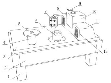
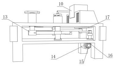
[0030] A steel bar bending machine for steel bar processing, such as Figure 1-4 As shown, it includes a workbench 3, the outer wall of the bottom of the workbench 3 is welded with a support seat 1, and the three peripheral walls of the workbench 3 are respectively fixed with baffles by bolts, and the front outer wall of the workbench 3 is fixed with a mounting plate 2 by bolts, The outer wall on one side of the top of the workbench 3 is fixed with a case 11 by bolts. Two air outlets 12 are provided on the outer wall on one side of the case 11. The top outer wall of the case 11 is clamped with a water tank 10. The outer wall of the case 11 near the side of the water tank 10 is fixed by bolts. A water pump 9 is fixed, the bottom inner wall of the workbench 3 is provided with an arc-shaped intermittent mechanism 13, and the top inner wall of the workbench 3 near the side of the chassis 11 is provided with an air guide port 17, and the top outer wall of the workbench 3 is provided...

Embodiment 2

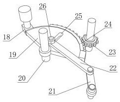
[0034] A steel bar bending machine for steel bar processing, such as Figure 4 As shown, in order to effectively promote the simultaneous bending of multiple steel bars; this embodiment makes the following improvements on the basis of embodiment 1: the inner wall of the top center of the installation groove is welded with a clamping column, and the outer wall of the clamping column is covered The clamping seat 27 is connected, and the top outer wall of the clamping seat 27 is respectively welded with a first stopper 28 and a second stopper 29; Between, and by starting the arc-shaped intermittent mechanism 13, the effect of simultaneously bending hoops of multiple steel bars is effectively promoted, and the efficiency of bending hoops of steel bars is greatly improved.


PUM


Abstract

The invention discloses a steel bar hoop-bending machine for steel bar processing, relates to the technical field of steel bar hoop bending, and aims to solve the problem of inaccurate steel bar curvature caused by high temperature. The steel bar hoop-bending machine specifically comprises a workbench; a supporting base is welded to the outer wall of the bottom of the workbench; baffles are fixedto three circumferential outer walls of the workbench through bolts; a mounting plate is fixed to the outer wall of the front face of the workbench through bolts; a chassis is fixed to the outer wallof one side of the top of the workbench through bolts; two air outlets are arranged on the outer wall of one side of the chassis; a water tank is clamped to the outer wall of the top of the chassis; awater pump is fixed to the outer wall of the side, close to the water tank, of the chassis through bolts; an arc-shaped intermittent mechanism is arranged on the inner wall of the bottom of the workbench; an air guide opening is arranged on the inner wall of the top of the side, close to the chassis, of the workbench; and an arc-shaped slideway is arranged on the outer wall of the top of the workbench. According to the steel bar hoop-bending machine provided by the invention, the curvature of steel bars can be guaranteed, the working efficiency of workers is promoted to a certain extent, andthe efficiency and quality of steel bar hoop bending are improved.

Description

technical field [0001] The invention relates to the technical field of steel bar bending hoops, in particular to a steel bar hoop bending machine for steel bar processing. Background technique [0002] The hoop bending machine is a processing tool for steel bars, which can be better processed into specified angles and models. Hoop bending machines are generally divided into semi-automatic hoop bending machines and fully automatic hoop bending machines. With the continuous development of the numerical control industry, more and more industries and enterprises have used hoop bending machines. According to different usage requirements in different situations, for steel bars , It is often necessary to perform a series of mechanical operations on it, such as stretching, straightening, cutting, bending hoops, etc. [0003] After retrieval, the Chinese patent application number is CN201420569268.2, which discloses a head for a steel bar hoop bending machine and a steel bar hoop be...

Claims


Application Information

Patent Timeline
Patent Type & Authority Applications(China)
IPC IPC(8): B21F1/00B21D37/16
CPCB21F1/00B21D37/16
Inventor 张光伟陈积光张光胜
Owner 冠县德汇商贸有限公司
Why Eureka
Try Eureka