Grinding device with function of adjusting angle of conical roller and method

An adjustable, tapered roller technology, used in grinding drives, grinding machines, manufacturing tools, etc., to solve problems such as uneven force, inapplicability, and impact on stability

Active Publication Date: 2020-12-29
佛山市科普卓机械制造有限公司
View PDF15 Cites 10 Cited by
  • Summary
  • Abstract
  • Description
  • Claims
  • Application Information

AI Technical Summary

Problems solved by technology

[0006] The above inventions and practical applications have the following disadvantages: in the first case, the two groups of clamping blocks are driven close to each other through the extension of the output end of the cylinder, and a semi-conical arc-shaped slot is opened on the inner side of the clamping block, which conforms to the shape of the tapered roller. The tapered roller is clamped, and rubber pads are provided on the inside of the slot to protect the surface of the tapered roller. The two clamping blocks are provided with semi-conical arc-shaped slots, and the inner wall is also provided with rubber pads. Due to the tapered roller itself It is in the shape of a cone. Clamping it with two semi-conical arc-shaped slots will cause uneven force, and the rubber pad will affect its stability, so it is not suitable. In the second invention, the first tapered roller device and The conical surface of the second tapered roller device is parallel to the upper surface of the roller table, and the conical surface of the first tapered roller device is in the same plane as the upper surface of the roller table, and the conical surface of the first tapered roller and the upper surface of the roller table are in the same plane , the rotation direction of the first conical roller device is the same as that of the roller table. When the tapered roller device turns, it will drive the wooden board to be clamped between the two tapered rollers, but this will sometimes cause stagnation, and the friction between the wooden board and the tapered rollers will increase, which will make the board less powerful.

Method used


Image

  • Grinding device with function of adjusting angle of conical roller and method
  • Grinding device with function of adjusting angle of conical roller and method
  • Grinding device with function of adjusting angle of conical roller and method

Examples


Embodiment Construction

[0050] The technical solutions of the present invention will be further described below in conjunction with the accompanying drawings and through specific implementation methods.

[0051] Wherein, the accompanying drawings are only for illustrative purposes, showing only schematic diagrams, rather than physical drawings, and should not be construed as limitations on this patent; in order to better illustrate the embodiments of the present invention, some parts of the accompanying drawings will be omitted, Enlarged or reduced, does not represent actual product size.

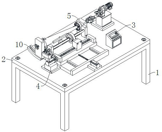
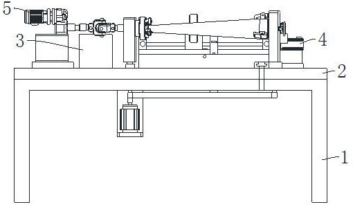
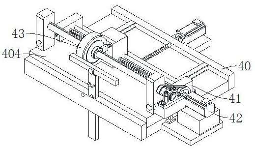
[0052] refer to Figure 1 to Figure 18 The shown grinding device has the function of adjusting the angle of the tapered roller, including a workbench 1 and a bottom plate 2, and also includes a controller 3, a grinding mechanism 4 and an adjustment mechanism 5, and the bottom plate 2 is fixed on the workbench 1 At the top, the controller 3 is fixedly arranged on one side of the top of the base plate 2. The grindi...


PUM


Abstract

The invention relates to the technical field of cone roller grinding, and in particular relates to a grinding device with the function of adjusting the angle of a conical roller and a method. The grinding device comprises a workbench and a bottom plate, and further comprises a controller, a grinding mechanism and an adjusting mechanism, wherein the bottom plate is fixedly arranged at the top of the workbench, the controller is fixedly arranged on one side of the top of the bottom plate, a grinding assembly comprises a first-stage sliding assembly, a second-stage sliding assembly, a first-stagedriving assembly and a polishing assembly, and the adjusting mechanism comprises a three-jaw chuck, a second-stage driving assembly, a clamping assembly and a rotating assembly. According to the grinding device and the grinding method, by clamping and fixing the conical roller, the position of the conical roller can be self-adaptively adjusted so that an inclined curved surface at one end of theconical roller becomes a horizontal curved surface; by controlling the controller, the conical roller can be accurately ground by a grinding wheel; and therefore, the grinding device is safe, efficient, accurate and controllable, and the grinding efficiency of the conical roller is greatly improved.

Description

technical field [0001] The invention relates to the technical field of tapered roller grinding, in particular to a grinding device and method capable of adjusting the angle of a tapered roller. Background technique [0002] Cone rollers are currently widely used mechanical components, such as curved conveyors, roller presses, etc., can be used in cone rollers. Although the cone rollers are not standard parts, they have gradually formed a certain production scale in the industry. The important parameters of the cone rollers are Large end diameter, small end diameter, cone length and taper. [0003] However, the surface of the cone roller needs to be ground during production and processing. Because its outer surface is cone-shaped, it is not easy to process and grind. Sticking and wear, secondary grinding is required to achieve a smooth and flat effect. At present, the existing machining accuracy is low, and the taper is not easy to control. The surface of the tapered roller ...

Claims


Application Information

Patent Timeline
Patent Type & Authority Applications(China)
IPC IPC(8): B24B5/14B24B5/37B24B41/00B24B41/06B24B47/00B24B47/12B24B47/16B24B47/20B24B47/22B24B49/00
CPCB24B5/14B24B5/37B24B41/062B24B47/00B24B49/00B24B47/22B24B47/12B24B47/16B24B41/007B24B47/20
Inventor 张国军洪美根
Owner 佛山市科普卓机械制造有限公司
Why Eureka
Try Eureka