Constant-force conduction device

A transmission device and guide device technology, applied in the field of force transmission, can solve problems such as complex force control algorithms, system damage, collision impact, etc., and achieve the effect of good force bearing, consistency, and small output force fluctuations

Pending Publication Date: 2020-12-29
HRG INT INST FOR RES & INNOVATION
View PDF0 Cites 1 Cited by
  • Summary
  • Abstract
  • Description
  • Claims
  • Application Information

AI Technical Summary

Problems solved by technology

[0002] At present, most of the research on fine manipulation technology of robots in unknown environments is realized through force control technology, and closed-loop control is carried out through force control algorithms. Due to the impact of collision, the signal of the force or torque sensor is easily overwhelmed by the interference signal, causing the force control algorithm to be very complicated or invalid; it may even exceed the range of the force or torque sensor, causing the risk of system damage

Method used


Image

  • Constant-force conduction device
  • Constant-force conduction device
  • Constant-force conduction device

Examples


Embodiment Construction

[0032]The application will be further described in detail below in conjunction with the drawings.

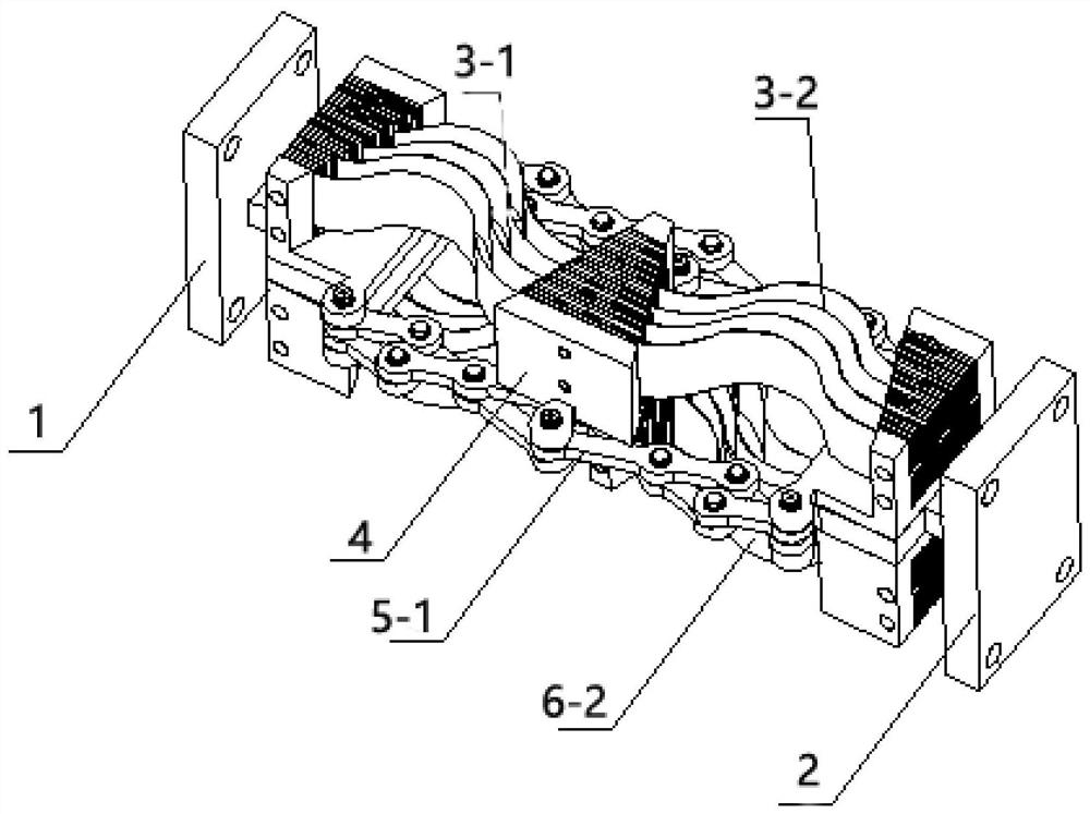
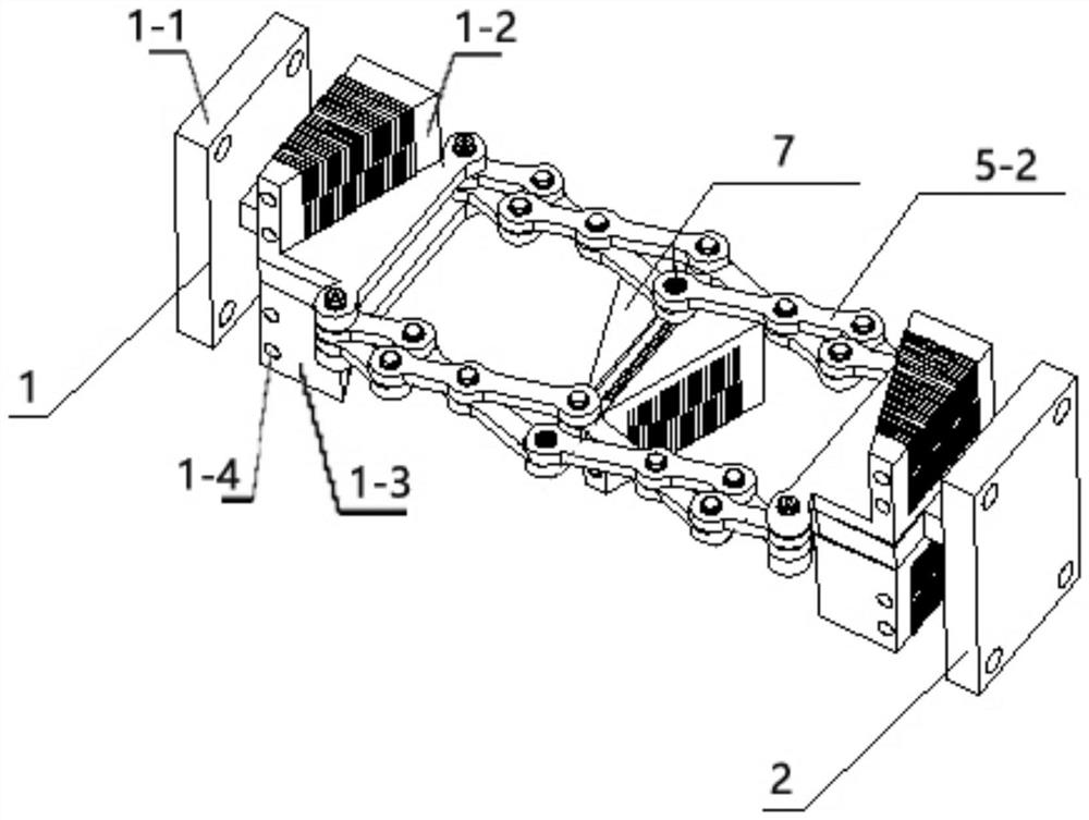
[0033]figure 1 Shows a schematic structural diagram of a constant force transmission device according to an embodiment of the present application,figure 2 It shows a schematic diagram of a partial structure of a constant force transmission device according to an embodiment of the present application.

[0034]According to an embodiment of the present invention, the constant force transmission device includes a force input end, a force output end, an upper force transmission member, a first intermediate guide device, and a connecting rod assembly, wherein the upper force transmission member includes a first upper force transmission member and a first upper force transmission member. Two upper force transmission elements, the connecting rod assembly includes a first connecting rod assembly, one end of the first upper force transmission element is connected to the force input end, the other end...


PUM


Abstract

The invention aims to provide a constant-force conduction device. The constant-force conduction device comprises a force input end, a force output end, an upper force conduction piece, a first middleguide device and a connecting rod assembly, wherein the upper force conduction piece comprises a first upper force conduction piece and a second upper force conduction piece; the connecting rod assembly comprises a first connecting rod assembly; one end of the first upper force conduction piece is connected with the force input end, and the other end of the first upper force conduction piece is connected with a first end of the first middle guide device; one end of the second upper force conduction piece is connected with a second end of the first middle guide device, and the other end of thesecond upper force conduction piece is connected with the force output end; and one end of the first connecting rod assembly is connected with the force input end, the other end of the first connecting rod assembly is connected with the force output end, and the middle part of the first connecting rod assembly is connected with the first middle guide device. Through the arrangement for the connecting rod assembly, constant-force output is achieved; and the constant-force conduction device is simple in structure, and easy to machine and manufacture.

Description

Technical field[0001]This application relates to the field of force transmission, and in particular to a constant force transmission device.Background technique[0002]At present, most of the research on the precision operation technology of robots in unknown environments is achieved through force control technology and closed-loop control through force control algorithms. However, operating in an unknown environment may cause the robot's end-effector to be overloaded or subjected to transient mutations. Under the impact of collision, the signal of the force or torque sensor is easily overwhelmed by interference signals, resulting in a very complicated or invalid force control algorithm; it may even exceed the range of the force or torque sensor, which may cause system damage.[0003]Therefore, the existing precision operation methods of robots based on force control will bring a series of problems to the cost of system software and hardware, operation safety and reliability. It is nece...

Claims


Application Information

Patent Timeline
Patent Type & Authority Applications(China)
IPC IPC(8): B25J11/00B25J19/00
CPCB25J11/0065B25J19/00
Inventor 张林松何亮赵龙海金小飞李文兴于振中
Owner HRG INT INST FOR RES & INNOVATION
Why Eureka
Try Eureka