Auxiliary support of building wall drilling machine

A technology for auxiliary brackets and drilling machines, which is applied in the direction of stone processing tools, work accessories, manufacturing tools, etc. It can solve the problems of wall damage to the wall, affecting the operation of workers, and a large amount of waste and dust. Work stability, reduce the pollution area, reduce the effect of vibration

Inactive Publication Date: 2020-12-29
FUZHOU GULOU TONGZHENG TECH CO LTD
View PDF0 Cites 0 Cited by
  • Summary
  • Abstract
  • Description
  • Claims
  • Application Information

AI Technical Summary

Problems solved by technology

[0002] In our daily life, a drilling machine refers to a general term for machines and equipment that leave cylindrical holes or holes on a target by means of rotary cutting or rotary extrusion using a tool that is harder and sharper than the target. At present, the drilling of the building wall is still done by fixing the bracket on the wall, and then manually using the drilling machine to drill the hole. This method requires 2-3 workers to cooperate with the operation, and there is a certain damage to the wall when the bracket is built. At the same time, a large amount of waste and dust will be generated during the drilling process, which will pollute the surrounding area greatly and affect the operation of workers. An auxiliary support for a building wall drilling machine explained in the present invention can solve the above problems

Method used


Image

  • Auxiliary support of building wall drilling machine
  • Auxiliary support of building wall drilling machine
  • Auxiliary support of building wall drilling machine

Examples


Embodiment Construction

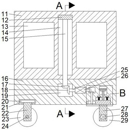
[0017] Combine below Figure 1-5 The present invention is described in detail, for the convenience of description, the orientations mentioned below are now specified as follows: figure 1 The projection relationship of itself is the same as the up, down, left, right, front, and rear directions.

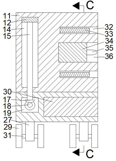
[0018] An auxiliary support for a building wall drilling machine according to the present invention includes a box body 11, and a dust removal device is arranged on the inner front side of the box body 11, and the dust removal device includes a box body 11 and an opening facing the The front dust removal chamber 32, the dust removal baffle 33 is slidably arranged in the dust removal chamber 32, and the left and right symmetrical dust removal sliding chamber 63 is connected to the rear end wall of the dust removal chamber 32, and the dust removal sliding chamber 63 is far away from the drilling machine 34. An electromagnetic plate 57 is fixed on one end wall, and an electric slider 58 ...


PUM


Abstract

The invention discloses an auxiliary support of a building wall drilling machine. The auxiliary support comprises a box body, wherein a dust removal device is arranged on the front side in the box body, the dust removal device comprises a dust removal cavity which is formed in the box body and provided with a forward opening, a dust removal baffle is arranged in the dust removal cavity in a sliding mode, dust removal sliding cavities which are symmetrical left and right are formed in the rear end wall of the dust removal cavity in a communicating mode, electromagnetic plates are fixedly arranged on the end walls of the ends, far away from the drilling machine, of the dust removal sliding cavities, and electric sliding blocks are arranged on the end faces of the ends, close to the drillingmachine, of the electromagnetic plates in a sliding mode. According to the auxiliary support, the drilling machine can be directly fixed to carry out wall drilling work, meanwhile, the totally-closedbaffle is arranged around a drilled hole, so that waste chips and dust generated during wall drilling can be collected for treatment, the pollution area is greatly reduced, and the situation that thework of workers is influenced due to flying of the waste chips and the dust is avoided; and the wall drilling position can be adjusted, the support does not need to be repeatedly erected for drilling,and the operation is convenient and rapid.

Description

technical field [0001] The invention relates to the field of drilling machines, in particular to an auxiliary support for a drilling machine for building walls. Background technique [0002] In our daily life, a drilling machine refers to a general term for machinery and equipment that uses a tool that is harder and sharper than the target to leave cylindrical holes or holes on the target by rotary cutting or rotary extrusion. At present, the construction wall drilling still adopts fixing the bracket on the wall, and then manually using the drilling rig to drill the hole. This method requires 2-3 workers to cooperate with the operation, and the wall construction bracket will cause some damage to the wall. At the same time, a large amount of waste debris and dust will be generated during the drilling process, which will pollute the surrounding area and affect the operation of workers. The auxiliary support for a building wall drilling machine described in the present inventio...

Claims


Application Information

Patent Timeline
Patent Type & Authority Applications(China)
IPC IPC(8): B28D1/14B28D7/00B28D7/02
CPCB28D1/14B28D7/00B28D7/02
Inventor 刘立喜
Owner FUZHOU GULOU TONGZHENG TECH CO LTD
Why Eureka
Try Eureka