Hydraulic buffer device

A hydraulic buffer and hydraulic technology, applied in fluid pressure actuators, fluid pressure actuator system components, servo motor components, etc., can solve problems such as loud noise and affecting the service life of actuators

Pending Publication Date: 2020-12-29
武汉船舶通信研究所
View PDF0 Cites 1 Cited by
  • Summary
  • Abstract
  • Description
  • Claims
  • Application Information

AI Technical Summary

Problems solved by technology

[0003] Nowadays, hydraulic transmission technology is widely used in various mechanical products, but in the process of high-pressure liquid transmitting energy to

Method used


Image

  • Hydraulic buffer device
  • Hydraulic buffer device

Examples


Embodiment Construction

[0023] In order to make the object, technical solution and advantages of the present invention clearer, the present invention will be further described in detail below in conjunction with the accompanying drawings and embodiments. It should be understood that the specific embodiments described here are only used to explain the present invention, not to limit the present invention. In addition, the technical features involved in the various embodiments of the present invention described below can be combined with each other as long as they do not constitute a conflict with each other.

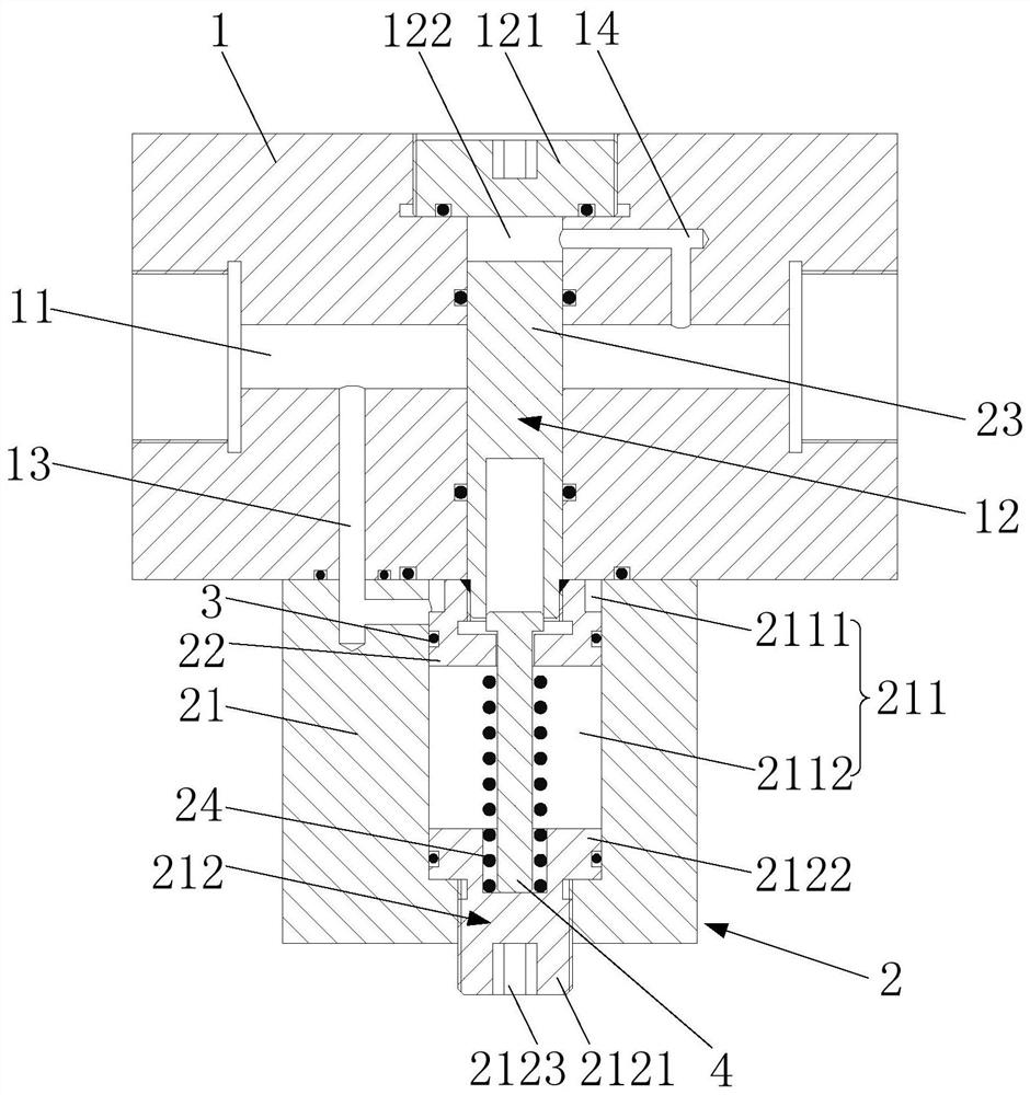
[0024] figure 1 is a cross-sectional view of the initial state of a hydraulic buffer device provided in this embodiment, such as figure 1 As shown, the hydraulic buffer device includes a main block 1 and a buffer assembly 2 .

[0025] The main block 1 has a hydraulic channel 11 and a control channel 12 , both ends of the hydraulic channel 11 run through the main block 1 , and the control chann...


PUM


Abstract

The invention discloses a hydraulic buffer device, and belongs to the technical field of hydraulic transmission. The hydraulic buffer device comprises a main block body and a buffer assembly, a hydraulic channel and a control channel are formed in the main block body, the two ends of the hydraulic channel penetrate through the main block body, and the control channel communicates with the hydraulic channel. The buffer assembly comprises a connecting block, a piston, a piston rod and an elastic piece, the connecting block is located on the main block body, a buffer cavity is formed in one sideof the connecting block and communicates with the control channel, the piston coaxially sleeves the first end of the piston rod, and the hydraulic channel communicates with a hydraulic cavity througha first flow channel. The outer circumferential wall of the second end of the piston rod is in sliding fit with the inner circumferential wall of the control channel to control the opening degree of the hydraulic channel, and the elastic piece is located in an elastic cavity. The hydraulic buffer device can prevent hydraulic pressure from generating instantaneous impact on execution elements, so that the service life of the execution elements is prolonged.

Description

technical field [0001] The invention belongs to the technical field of hydraulic transmission, and more specifically relates to a hydraulic buffer device. Background technique [0002] Hydraulic transmission refers to a transmission method that uses liquid as the working medium for energy transmission and control, specifically the use of liquid pressure for energy conversion. The use of hydraulic transmission technology in machinery can effectively simplify the structure of the machinery, reduce the weight of the machinery, reduce material consumption, reduce manufacturing costs, reduce labor intensity, and improve work efficiency and reliability. [0003] Nowadays, hydraulic transmission technology is widely used in various mechanical products, but in the process of high-pressure liquid transmitting energy to the actuator, it will cause a large instantaneous impact on the actuator, which will not only bring greater noise, but also affect the service life of actuators. Co...

Claims


Application Information

Patent Timeline
IPC IPC(8): F15B21/00F15B13/02
CPCF15B13/02F15B21/008
Inventor 刘卓耀肖定国吴罡吴建峰宰芹芹王昭肖青潘利兵李菁王超轮王凯淇王飞翔黄龙
Owner 武汉船舶通信研究所
Why Eureka
Try Eureka