Liquid-cooled battery system and control method of liquid-cooled battery system

A liquid-cooled battery and control method technology, which is applied in battery/fuel cell control devices, battery/battery traction, batteries, etc., can solve the impact, potential safety hazards of the whole vehicle, unfavorable safety of the vehicle battery pack, etc. problem, achieve the effect of ensuring safety, improving carrying capacity and avoiding excessive temperature difference

Active Publication Date: 2020-12-29
CHINA FIRST AUTOMOBILE
View PDF8 Cites 23 Cited by
  • Summary
  • Abstract
  • Description
  • Claims
  • Application Information

AI Technical Summary

Problems solved by technology

[0004] However, in the prior art, the cooling water pipe is arranged inside the vehicle-mounted battery pack. Once the cooling water pipe leaks, it will have a very adverse impact on the safety of the vehicle-mounted battery pack and the safety of the entire vehicle, causing great damage to the entire vehicle. Security risks

Method used


Image

  • Liquid-cooled battery system and control method of liquid-cooled battery system
  • Liquid-cooled battery system and control method of liquid-cooled battery system
  • Liquid-cooled battery system and control method of liquid-cooled battery system

Examples


Embodiment 1

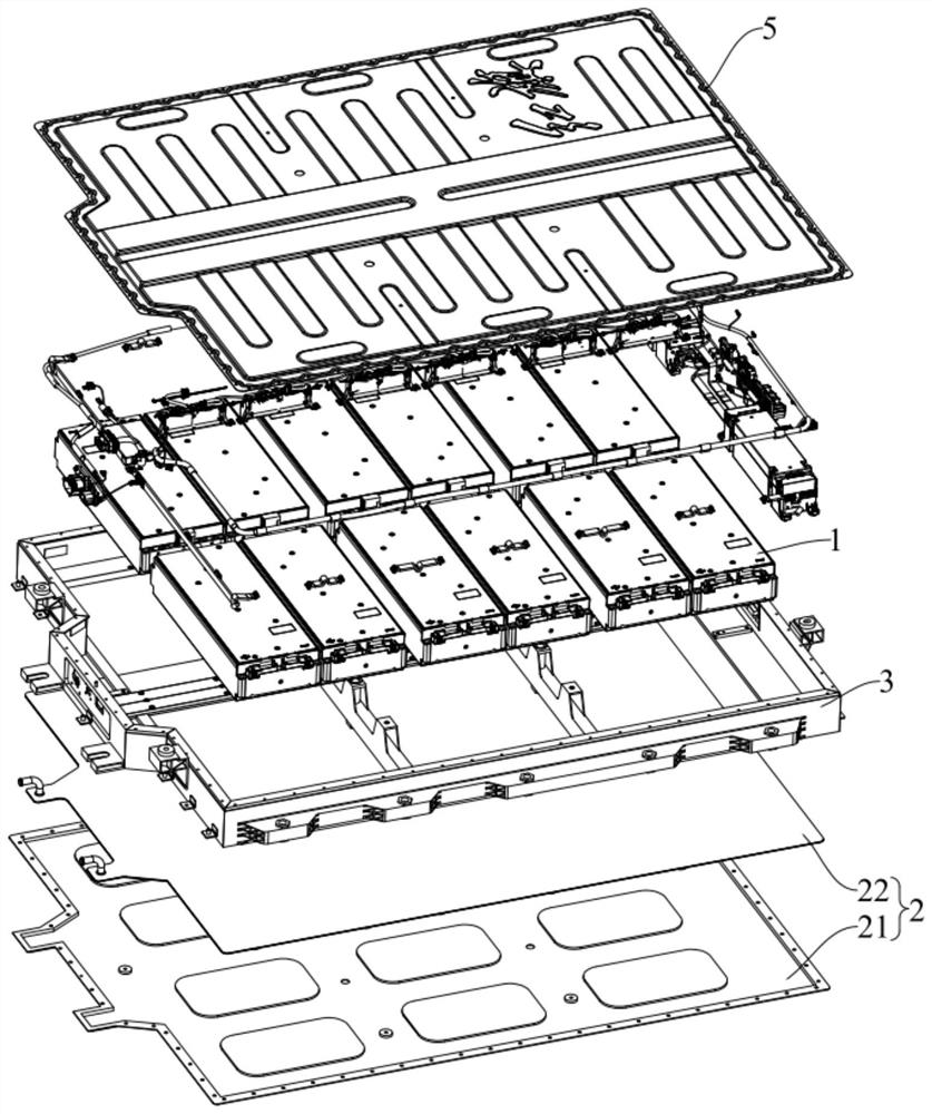
[0049] see Figure 1-Figure 7 , This embodiment provides a liquid-cooled battery system. Specifically, the liquid-cooled battery system is applied to an automobile, which can improve the safety of the battery module and further improve the safety performance of the entire vehicle.

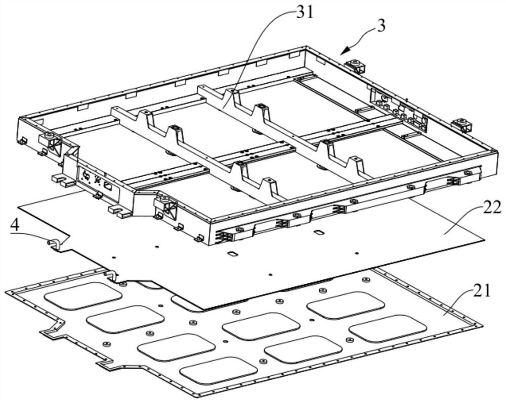
[0050] see figure 1 , figure 2 and Figure 4 , in this embodiment, the liquid-cooled battery system includes a battery module 1 and a cooling bearing part 2 .

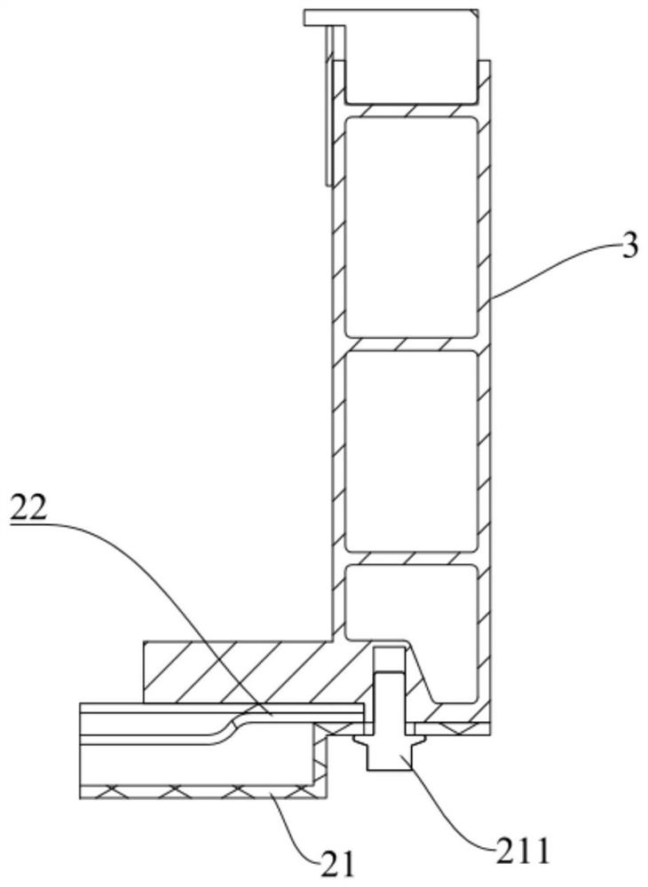
[0051]The cooling bearing part 2 includes a bottom guard plate 21 and a liquid cooling plate 22 arranged on the upper surface of the bottom guard plate 21. The battery module 1 is located on the upper surface of the liquid cooling plate 22. Inside the liquid cooling plate 22, there are several cooling plates along the first direction. The cooling channels 221 are arranged in sequence, and each cooling channel 221 has a liquid inlet and a liquid outlet, and the flow rate in each cooling channel 221 is the same.

[0052] In the liquid-co...

Embodiment 2

[0089] see Figure 8 This embodiment provides a method for controlling a liquid-cooled battery system, which is used to control the liquid-cooled battery system in Embodiment 1 to cool the battery module 1 .

[0090] Specifically, the liquid-cooled battery system further includes a cooling device, which is used to deliver cooling liquid into the liquid-cooled plate 22 . The battery module 1 includes several battery cells 11 .

[0091] The control method of the liquid-cooled battery system includes the following steps:

[0092] S1. Collect the first current temperature of several battery cells 11;

[0093] Specifically, in step S1, if the liquid-cooled battery system includes multiple battery modules 1, the first current temperature of all battery cells 11 is collected.

[0094] S2, judging whether the maximum value of the first current temperature of several batteries 11 is less than the first set temperature, if yes, then perform step S3; if not, then perform step S4;

[00...


PUM


Abstract

The invention discloses a liquid-cooled battery system and a control method of the liquid-cooled battery system, and belongs to the technical field of vehicle-mounted batteries. The liquid-cooled battery system comprises a battery module; and a cooling bearing part which comprises a bottom protection plate and a liquid cooling plate arranged on the upper surface of the bottom protection plate, wherein the battery module is located on the upper surface of the liquid cooling plate, a plurality of cooling flow channels sequentially arranged in the first direction are formed in the liquid coolingplate, each cooling flow channel is provided with a liquid inlet and a liquid outlet, and the flow in each cooling flow channel is the same. The control method of the liquid-cooled battery system is used for controlling the cooling of the liquid-cooled battery system. The integrated efficiency of the liquid-cooled battery system can be improved, the leakage risk of the cooling liquid of the liquid-cooled battery system is reduced, and the safety performance of the liquid-cooled battery system is improved.

Description

technical field [0001] The invention relates to the technical field of vehicle batteries, in particular to a liquid-cooled battery system and a control method for the liquid-cooled battery system. Background technique [0002] With the continuous development of new energy technology, the application of new energy vehicles is becoming more and more extensive. [0003] The on-board battery pack powers the vehicle while driving. During driving, the on-board battery pack will heat up, and when the temperature of the on-board battery pack is too high, certain safety hazards will arise. Therefore, in the prior art, cooling water pipes are generally provided inside the vehicle battery pack to cool down the temperature of the vehicle battery pack. [0004] However, in the prior art, the cooling water pipe is arranged inside the vehicle-mounted battery pack. Once the cooling water pipe leaks, it will have a very adverse impact on the safety of the vehicle-mounted battery pack and t...

Claims


Application Information

Patent Timeline
Patent Type & Authority Applications(China)
IPC IPC(8): H01M10/613H01M10/617H01M10/625H01M10/635H01M10/633H01M10/6554H01M10/6556H01M10/6568H01M2/10B60L50/64B60L58/26
CPCH01M10/613H01M10/617H01M10/625H01M10/635H01M10/633H01M10/6554H01M10/6556H01M10/6568B60L50/64B60L58/26H01M2220/20Y02T10/70Y02E60/10
Inventor 周琪卢军李阳王明乔延涛尹芳芳于鹏王振涛
Owner CHINA FIRST AUTOMOBILE
Why Eureka
Try Eureka