Battery protection circuit

A protection circuit and voltage protection technology, applied in the electronic field, can solve the problems of damage to the chip, increase the chip area and cost, and achieve the effect of reducing the chip area and cost and high withstand voltage.

Pending Publication Date: 2020-12-29
SHENZHEN ICM MICROELECTRONICS CO LTD
View PDF0 Cites 7 Cited by
  • Summary
  • Abstract
  • Description
  • Claims
  • Application Information

AI Technical Summary

Problems solved by technology

[0003] The invention provides a battery protection circuit to solve the problems that the existing battery protection circuit uses a low-voltage switch tube and is easily broken down to damage the chip, and the chip area and cost are increased when the high-voltage switch tube is used.

Method used


Image

  • Battery protection circuit
  • Battery protection circuit
  • Battery protection circuit

Examples


Embodiment approach

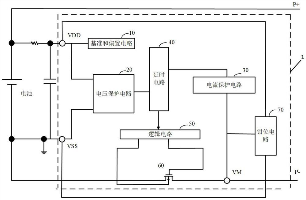
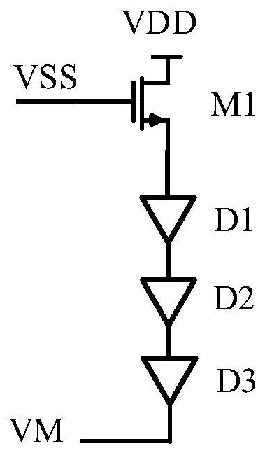
[0060] Optionally, as mentioned above, when the clamping circuit 70 is working, the voltage drop between the second terminal and the third terminal is smaller than the source-drain breakdown voltage VDS of the switch tube. As an implementation manner, the clamping circuit 70 includes an NMOS transistor M1 and a diode string, and the diode string includes several diodes connected in series;

[0061] The drain of the NMOS transistor M1 is connected to the power supply voltage sampling point, the gate is connected to the ground with the negative pole of the battery, and the source is connected to the positive pole of the diode string;

[0062] The cathode of the diode string is connected to the sampling point of the loop current.

[0063] Here, when the clamping circuit 70 is working, the voltage drop between the gate of the NMOS transistor M1 and the cathode of the diode string is smaller than the source-drain breakdown voltage VDS of the switch transistor. The number of diodes...


PUM


Abstract

The invention provides a battery protection circuit which is characterized in that a clamping circuit is added to an existing battery protection circuit, a first end of the clamping circuit is connected with a power supply voltage sampling point, a second end of the clamping circuit and a negative electrode of a battery are connected to the ground, and a third end of the clamping circuit is connected with a loop current sampling point; and the loop current sampling point is located at the negative electrode of a charging power supply or load side. The clamping circuit receives electric energyfrom a power supply voltage sampling point, detects a voltage value on a loop current sampling point, and carries out clamping processing on the loop current sampling point when negative high voltageoccurs at the loop current sampling point, thereby effectively solving a problem that a chip is damaged because a low-voltage switching tube is broken down by the negative high voltage. The high voltage resistance of the battery protection chip is achieved while the low-voltage switching tube is used, and the area and cost of the chip are reduced.

Description

technical field [0001] The invention relates to the field of electronic technology, in particular to a battery protection circuit. Background technique [0002] The existing battery protection chip includes an over-discharge protection circuit and an over-charge protection circuit for detecting the battery voltage, a discharge over-current protection circuit for detecting the loop current, a charging over-current protection and a short-circuit protection circuit, and a circuit for controlling the on-off of the charge-discharge switch tube. The switch tube control module realizes the protection of battery charge and discharge. However, the switch tube in the existing battery protection chip is mainly a low-voltage MOS tube, and the withstand voltage of the device is about 10V. The tube is damaged, causing the battery protection chip to fail to work normally. And replacing the switching tube with a high-voltage tube will greatly increase the chip area and cost. Contents of...

Claims


Application Information

Patent Timeline
IPC IPC(8): H02J7/00H02H7/18
CPCH02J7/0029H02J7/0036H02J7/00302H02J7/00306H02H7/18
Inventor 李杰白青刚杨小华
Owner SHENZHEN ICM MICROELECTRONICS CO LTD
Why Eureka
Try Eureka