
Electromagnetic engine

An electromagnetic engine and engine technology, applied in the direction of electrical components, electromechanical devices, etc., can solve the problems of combustion exhaust gas pollution of the environment, consumption of large fossil energy, large consumption of fossil energy, etc., to achieve simple structure, saving and protecting the environment, and easy production and implementation Effect

Pending Publication Date: 2020-12-29
陈雪松
View PDF0 Cites 0 Cited by
  • Summary
  • Abstract
  • Description
  • Claims
  • Application Information

AI Technical Summary

Problems solved by technology

[0003] The purpose of the present invention is to provide an electromagnetic engine that uses electromagnetic force to drive the crankshaft to rotate, which is simple in structure and reliable in operation, and effectively solves the problems of large consumption of fossil energy caused by the use of traditional internal combustion engines and pollution of the environment by combustion exhaust gases. The internal combustion engine consumes a lot of fossil energy and the combustion exhaust gas pollutes the environment

Method used


Image

  • Electromagnetic engine
  • Electromagnetic engine

Examples


Embodiment 1

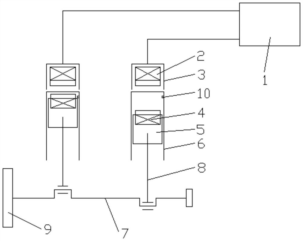
[0022] This embodiment provides an electromagnetic motor;

[0023] Such as figure 1 As shown, the electromagnetic motor in this embodiment includes a cylinder 6 and a force chamber 3 located above the cylinder 6. A matching piston 5 is arranged in the cylinder 6, and the piston 5 is connected to the crankshaft 7 through a connecting rod 8. connected, the top of the piston 5 is provided with a lower electromagnet 4, the force chamber 3 is provided with an upper electromagnet 2 corresponding to the lower electromagnet 4, and the upper electromagnet 2 and the lower electromagnet 4 The magnetic poles are the same after being energized, and a controller for controlling the power on and off of the upper electromagnet 2 and the lower electromagnet 4 is also included.

[0024] In the present invention, a lower electromagnet is arranged on the top of the piston, and an upper electromagnet corresponding to the lower electromagnet is arranged in the force chamber, and the power on and o...

Embodiment 2

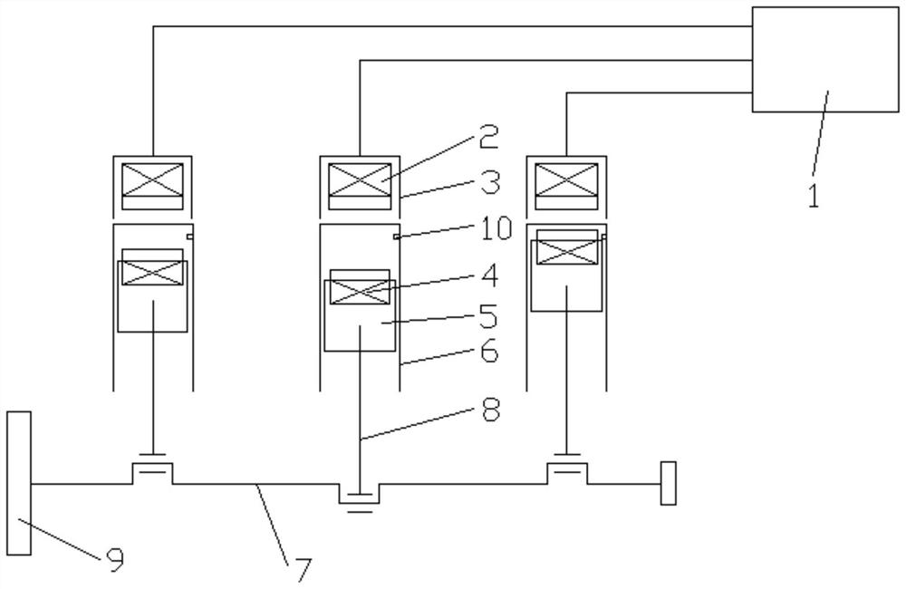
[0034] This embodiment provides another electromagnetic motor;

[0035] Such as figure 2 As shown, the electromagnetic motor in this embodiment includes a cylinder 6 and a force chamber 3 located above the cylinder 6. A matching piston 5 is arranged in the cylinder 6, and the piston 5 is connected to the crankshaft 7 through a connecting rod 8. connected, the top of the piston 5 is provided with a lower electromagnet 4, the force chamber 3 is provided with an upper electromagnet 2 corresponding to the lower electromagnet 4, and the upper electromagnet 2 and the lower electromagnet 4 The magnetic poles are the same after being energized, and a controller for controlling the power on and off of the upper electromagnet 2 and the lower electromagnet 4 is also included.

[0036] In the present invention, a lower electromagnet is arranged on the top of the piston, and an upper electromagnet corresponding to the lower electromagnet is arranged in the force chamber, and the power on...


PUM


Abstract

The invention discloses an electromagnetic engine. The electromagnetic engine comprises an air cylinder and an original force chamber arranged above the air cylinder, wherein a matched piston is arranged in the air cylinder and connected with a crankshaft through a connecting rod, a lower electromagnet is arranged at the top of the piston, and an upper electromagnet corresponding to the lower electromagnet is arranged in the original force chamber, the upper electromagnet and the lower electromagnet have the same magnetic pole after being powered on, and the controller is used for controllingthe power-on and power-off of the upper electromagnet and the lower electromagnet. After an engine is started and a piston moves to an upper dead center, a controller controls an upper electromagnet and a lower electromagnet to be powered on, due to the fact that magnetic poles of the upper electromagnet and the lower electromagnet are the same after the upper electromagnet and the lower electromagnet are powered on, the piston can move downwards under the action of repulsive force, and the crankshaft can be driven to continuously rotate through alternate reciprocation; when the electromagnetic engine operates, fossil fuel does not need to be continuously consumed, combustion tail gas emission is avoided, and energy conservation and environment protection are facilitated.

Description

technical field [0001] The invention relates to the field of engines, in particular to an electromagnetic engine. Background technique [0002] The engine is a power machine that converts other energy into mechanical energy to drive other mechanical work. Traditional engines are mainly internal combustion engines. Whether it is a gasoline engine or a diesel engine, fossil fuels are used as the main energy source. On the one hand, it consumes a lot of energy. energy. With the rapid growth of the application of internal combustion engines, the consumption of energy such as gasoline and diesel has increased significantly, which has led to the increasing shortage of non-renewable resources such as gasoline and diesel. Therefore, it is urgent to develop new engines to replace traditional internal combustion engines. Contents of the invention [0003] The purpose of the present invention is to provide an electromagnetic engine that uses electromagnetic force to drive the crank...

Claims


Application Information

Patent Timeline
Patent Type & Authority Applications(China)
IPC IPC(8): H02K53/00
CPCH02K53/00
Inventor 陈雪松
Owner 陈雪松
Learn More